Hello! Welcome to the next lesson in our journey through quantum gates.
In our previous session, we saw how sequences of single-qubit gates can be combined through matrix multiplication to create more complex operations. We learned that the order of multiplication is the reverse of the order in a circuit diagram, and we used Qiskit's statevector_simulator to verify our calculations.
So far, our qubits have lived in isolation. Today, we'll change that. We are moving into the realm of multi-qubit gates, which allow qubits to interact with each other. This is a crucial step, as these interactions are what enable uniquely quantum phenomena like entanglement and form the backbone of powerful quantum algorithms.
Our goal for this lesson is to apply the CNOT, SWAP, and Controlled-Z gates to describe their effect on multi-qubit states. We will explore how each gate works conceptually, represent them with matrices, and understand their impact on the state of a two-qubit system.
1. Moving to Two Qubits
Before we dive into the gates, let's quickly formalize the two-qubit system. As we saw when we first discussed tensor products, a two-qubit system is described by a state vector in a four-dimensional space. The computational basis states are:
Remember that Qiskit uses a little-endian convention, so the state corresponds to qubit 1 and qubit 0. Operations on this 4D space will be represented by 4x4 unitary matrices.
2. The Controlled-NOT (CNOT) Gate
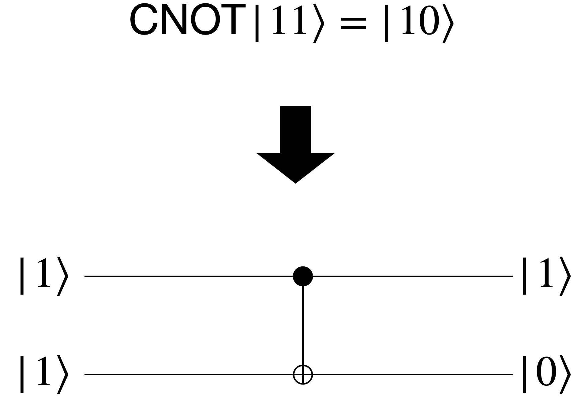
The CNOT gate is one of the most fundamental two-qubit gates. It acts as a "quantum conditional statement": it applies a NOT (X) gate to a target qubit, but only if a separate control qubit is in the state .
- If control is : The target qubit is unchanged.
- If control is : The target qubit is flipped ().
The CNOT gate is represented in a circuit diagram by a filled circle (●) on the control qubit's wire, connected by a line to a circled-plus (⊕) on the target qubit's wire.
The following video provides a great visual and mathematical introduction to the CNOT and other two-qubit gates.
2-Qubit Gates Matrix Representations & Quantum Circuits, Controlled Not/CNOT, Controlled Z/CZ, SWAP
This video from the channel Elucyda introduces the matrix representations for common two-qubit gates.
Please watch the section explaining the Controlled-NOT (CNOT) gate. Pay close attention to how the matrix representation changes depending on which qubit is the control and which is the target.
The CNOT Matrix
As the video explains, the matrix for a CNOT gate depends on which qubit is the control. Let's analyze the case where qubit 1 is the control and qubit 0 is the target, which corresponds to cx(1, 0) in Qiskit.
The transformation rules are:
- (control is 0, target unchanged)
- (control is 0, target unchanged)
- (control is 1, target flips from 0 to 1)
- (control is 1, target flips from 1 to 0)
This leads to the following 4x4 matrix:
Notice how this matrix swaps the third and fourth columns of the identity matrix, effectively swapping the basis states and .
3. The SWAP Gate
The SWAP gate does exactly what its name implies: it exchanges the states of two qubits. If you have a two-qubit state , the SWAP gate transforms it to .
Its transformation on the basis states is:
The states and are unaffected.
The matrix for the SWAP gate is:
This time, the matrix swaps the second and third columns of the identity matrix, corresponding to the swap between and .
A key insight, relevant to your interest in circuit implementation, is that the SWAP gate is not always a fundamental, physical operation. It can be constructed from three CNOT gates. This is a great example of gate composition.
Get started with Qiskit in the classroom
This IBM Quantum Learning page explains the SWAP gate and its decomposition.
Please read the section on the SWAP gate. Pay attention to the truth table, the matrix form, and especially the circuit diagram showing how qc.swap(0, 1) can be decomposed into a sequence of CNOTs. This reinforces what we learned about gate composition in the last lesson. You can also try the "Check your understanding" exercise to verify the decomposition using matrix multiplication, which is excellent practice.
The need for SWAP gates is very practical. On physical quantum hardware, not all qubits are directly connected. Given your background in electronics, you can think of this as a chip layout problem. If you need to perform a CNOT between two qubits that aren't physically adjacent, you must use a series of SWAP gates to "route" the quantum information across the chip, which adds overhead to the algorithm.
4. The Controlled-Z (CZ) Gate
The Controlled-Z (CZ) gate is another essential two-qubit gate. Like the CNOT, it has a control and a target. It applies a Z gate (a phase flip of -1) to the target qubit if and only if the control qubit is .
- If control is : Target is unchanged.
- If control is :
- If target is , nothing happens (since ).
- If target is , its phase is flipped ().
So, the only state that is affected is , which becomes .
The matrix for the CZ gate is elegantly simple:
It's an identity matrix with the bottom-right element flipped to -1.
A crucial property of the CZ gate is its symmetry. Unlike the CNOT gate, it doesn't matter which qubit you label as control and which as target—the resulting operation is identical. Applying a phase flip when both qubits are is a symmetric condition.
2-Qubit Gates Matrix Representations & Quantum Circuits, Controlled Not/CNOT, Controlled Z/CZ, SWAP
Let's return to the Elucyda video to see the explanation for the CZ gate.
Watch the segment on the Controlled-Z gate. The video clearly explains its matrix form and highlights its symmetric nature, which we just discussed. It also shows how a CZ gate can be constructed from a CNOT gate by "sandwiching" the target with Hadamard gates.
This relationship, , is extremely useful. It means that if a quantum computer can physically implement CNOT and single-qubit gates, it can also perform CZ operations, and vice-versa.
Conclusion
In this lesson, we expanded our toolkit from single-qubit gates to the essential two-qubit gates that enable qubits to interact. These interactions are the source of quantum computing's power.
Key Takeaways:
- Multi-qubit gates are represented by larger (e.g., 4x4 for two qubits) unitary matrices.
- The CNOT gate acts as a conditional bit-flip, flipping a target qubit if a control qubit is . Its matrix form is asymmetric and depends on the choice of control/target.
- The SWAP gate exchanges the states of two qubits and is crucial for routing information on physical hardware. It can be constructed from three CNOT gates.
- The Controlled-Z (CZ) gate applies a conditional phase-flip, affecting only the state. It is symmetric, and it can be constructed from a CNOT and two Hadamard gates.
Preview of the Next Lesson:
We've mentioned that these gates can create entanglement, but we haven't done it explicitly yet. In our next lesson, we will use the CNOT and Hadamard gates to do just that. We will construct a Bell state circuit, which generates one of the simplest yet most profound examples of quantum entanglement, and begin to explore what makes this phenomenon so different from anything in the classical world.