Hello! Welcome back to our course.
In our last lesson, we took a precisely wound coil and transformed it into a solid, monolithic block using Vacuum Pressure Impregnation (VPI). We learned that this void-free composite structure is essential for the electrical, thermal, and mechanical integrity of a high-field magnet. However, even this robust, epoxy-impregnated coil cannot withstand the immense electromagnetic forces of a high-field pulse on its own. It is strong, but brittle, and would shatter under the violent, multi-megajoule impacts of the Lorentz force.
This brings us to today's learning outcome: Detail the assembly procedures for reinforced coils, including the mounting of pre-compression and support structures. We will explore how the VPI-cured coil is integrated into a larger mechanical assembly designed to contain these forces. We'll focus on the critical concept of pre-compression and examine two distinct, practical strategies for building a coil assembly that can survive repeated pulses to tens of Tesla.
1. The Principle of Pre-Compression
During a pulse, the Lorentz force, , creates an immense outward radial pressure (leading to hoop stress) and strong axial forces that try to stretch or crush the coil. The epoxy-fiberglass-copper composite of the coil is significantly stronger under compression than it is under tension. If the electromagnetic forces are large enough to pull the composite into a state of high tension, micro-cracks can form and propagate, leading to failure.
The solution is to build the coil in a state of pre-compression. We apply a large, static compressive force to the coil before it is ever pulsed. When the magnetic pulse occurs, the outward Lorentz force must first overcome this inward pre-compression before it can even begin to put the windings into tension.
A classic analogy is a wooden barrel. The steel hoops are heated, placed around the wooden staves, and allowed to cool. As they cool and contract, they place the staves under high compression. When the barrel is filled with liquid, the outward pressure from the liquid is counteracted by this pre-compression, ensuring the staves remain tightly sealed. We use the same principle, but the forces are orders of magnitude greater.
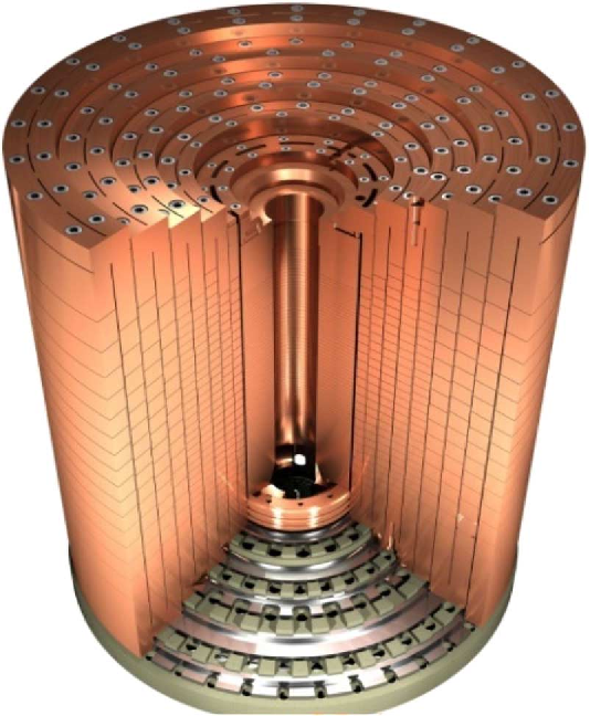
Today we will examine two primary methods for achieving this reinforcement and pre-compression.
2. Assembly Strategy 1: Nested, Shrink-Fitted Coils
One established method, particularly for very large and powerful magnets, is to build the coil in several concentric segments. Each segment is wound and impregnated separately. The inner segments experience the highest fields and forces, while the outer segments act as reinforcement. The assembly process relies on precision machining and interference fits (or shrink-fits).
Let's explore the assembly of a multi-segment pulsed magnet designed at Brookhaven National Lab (BNL).
Design Report BNL - E951 15T Pulsed Magnet for Mercury ...
This design report for a 15 T pulsed magnet provides a practical, step-by-step description of how a multi-segment coil is assembled. It gives a clear picture of the manufacturing and assembly sequence.
Please read section 17.0 'Manufacture and Assembly Approaches' (located near the end of the document, on page 29). Focus on the bullet points under 'Assembly and Manufacture'. Pay attention to the sequence: winding on separate mandrels, applying and machining ribs, and the method of slipping coils onto one another.
From the reading, we can extract the key assembly steps:
-
Separate Fabrication: Each coil segment is layer-wound on its own precision mandrel and VPI-cured. This modular approach allows for phased manufacturing.
-
Precision Machining: After a segment is cured, its outer surface is machined to a precise diameter. If ribs are needed for cooling channels or structural support (as discussed in Section 5.10 of the report), they are applied and machined.
-
Shrink-Fitting: The report states, "Coils are slipped on to one another. – with a temperature difference if needed". This is a classic shrink-fit operation.
- The outer coil (or reinforcement shell) is heated, causing it to expand due to thermal expansion.
- The inner, completed coil segment (at room temperature or even cooled with liquid nitrogen) is inserted into the expanded outer shell.
- As the entire assembly returns to thermal equilibrium, the outer shell contracts, creating a massive compressive pressure on the inner coil. This pressure is the radial pre-compression.
-
Axial Pre-Compression: The report also mentions a "mechanical head closure" and that "The head is replaced, and bolts torqued." This refers to thick metal plates on the ends of the coil assembly, connected by large, high-strength bolts (tie rods). By tightening these bolts to a specific torque, a calculated compressive force is applied along the axis of the coil, pre-compressing it axially.
This nested-shell approach creates an extremely robust structure where the forces are transmitted from the innermost, highest-stressed coils outwards to the stronger, bulkier reinforcement layers.
3. Assembly Strategy 2: External Composite Reinforcement
An alternative and increasingly common strategy, especially for achieving a high strength-to-weight ratio, is to reinforce a single monolithic coil with an external wrapping of advanced composite fibers. Materials like S-glass, carbon fiber, or, for the highest performance, Zylon, are used. Zylon (PBO) is a synthetic polymer with a tensile strength significantly higher than steel at a fraction of the density.
Let's examine the construction of a novel "Foil Coil" that uses this exact technique.
A novel pulsed magnet for magnetic linear birefringence ...
This paper describes a pulsed magnet reinforced with Zylon fibers. It provides an excellent, modern example of composite reinforcement and the application of pre-stress. Given your experience with various materials, the properties of Zylon will be of particular interest.
Please read Section III. B. 'Realization' (starts on page 4). Focus on how the reinforcement is applied. Note the material used (Zylon), the method of application (winding), and the crucial detail about applying a high pre-stress.
The key takeaways from this paper are:
- External Winding: The Zylon fibers are wound directly onto the outside of the cured copper-Kapton coil. This is done on a winding machine that maintains high tension in the fiber.
- Applying Pre-Stress: The paper explicitly states: "Zylon fibers are applied with a high pre-stress around 700 MPa". This is a tremendous pressure, permanently squeezing the coil. This radial pre-compression ensures the copper windings are pressed firmly against the inner support body, preventing them from buckling inward or expanding outward during the pulse.
- Force Transmission: The paper includes Finite Element Analysis (FEA) models (Figure 3a), which are highly relevant to your computational interests. These simulations show exactly how the outward Lorentz forces generated in the copper foils are transmitted to and contained by the outer Zylon wrapping. The reinforcement is the structural backbone.
- Axial Reinforcement: This magnet also uses axial support structures. The paper mentions: "The extremities of the magnet are reinforced with two 25 mm thick stainless steel plates that are also used to fix the magnet, screwed with the M24 tie rods." Just like in the BNL design, these end plates and tie rods provide axial containment and pre-compression.
This method allows for the creation of very strong, yet relatively compact and lightweight magnets, as the reinforcement material is extremely efficient.
Test your understanding!
Imagine you are assembling a coil using the Zylon wrapping method. You notice that the winding tension on the Zylon fiber is accidentally set much lower than the specified 700 MPa pre-stress. What is the most likely failure mode for the coil when it is pulsed to its full design field, and why?
Show answer
The most likely failure mode is mechanical failure of the windings due to excessive tensile hoop stress. Without sufficient radial pre-compression, the outward Lorentz force will quickly overcome the small initial clamping force and put the copper/epoxy composite into a high state of tension. Since the composite is much weaker in tension than compression, it is likely to crack and fail. Furthermore, any small movement of the windings could lead to insulation damage and electrical arcing between turns.
Conclusion
We have seen that a cured coil is only the first step. The assembly process, which integrates this coil into a robust support structure, is what ultimately determines the magnet's performance and lifetime. This is a process of pure mechanical engineering, where precision machining, material science, and an understanding of stress and strain are paramount.
Key Takeaways:
- A cured magnet coil cannot withstand pulsed-field forces alone; it must be assembled into a reinforcing structure.
- Pre-compression is a core principle: a large static compressive load is applied to the coil to counteract the dynamic tensile Lorentz forces, keeping the coil composite from being pulled apart.
- Assembly can be done by shrink-fitting nested metallic shells, where thermal contraction creates radial pre-load.
- Alternatively, coils can be reinforced by winding them with high-strength composite fibers (like Zylon) under high tension.
- Axial forces are managed using thick end plates and high-strength tie rods, which are torqued to apply an axial pre-load.
Next Lesson Preview:
Our magnet is now fully wound, impregnated, and assembled into its reinforcement structure. It is, in principle, ready to be pulsed. The next logical step is to measure the field it produces. In our next lesson, we will address the learning outcome: "Design inductive pickup coils for magnetic field measurement and calculate their calibration factors." We will dive into the simple but powerful technique used to precisely measure the B(t) profile of a pulsed magnetic field.