Welcome back! In our first lesson, we established the fundamental concept that a transistor can act as an electronic switch, giving us a physical way to represent the binary values 0 and 1. This was a crucial first step in bridging the gap between abstract logic and physical hardware.
Today, we will zoom in on the environment where these transistors live: the electrical circuit. To build reliable logic gates, we need to understand and control the electrical properties that govern them. This lesson focuses on a core learning outcome: to simulate a simple circuit to visualize the relationship between voltage, current, and resistance. We will define these three fundamental quantities and see how they are interconnected through a principle known as Ohm's Law. By using an interactive simulation, you'll get a direct, visual feel for these concepts, which is essential before we begin constructing our own circuits.
The Holy Trinity of Electricity: Voltage, Current, and Resistance
Before we can manipulate electricity to perform computations, we must understand its basic characteristics. The behavior of electricity in simple circuits is primarily described by three quantities: voltage, current, and resistance.
A very effective way to build an intuition for these concepts is the "water tank" analogy. Imagine a tank of water with a hose at the bottom.
- Voltage (V) is like the water pressure. It's the potential energy difference between two points. A tank filled with more water creates more pressure at the hose outlet. In electronics, this "pressure" is what pushes electrons through a circuit. It is measured in Volts.
- Current (I) is like the water flow rate. It's the rate at which charge (carried by electrons) flows past a point in the circuit. More pressure (voltage) results in a higher flow rate (current). It is measured in Amperes (or Amps).
- Resistance (R) is like the narrowness of the hose. It's a material's tendency to oppose the flow of current. A narrower hose restricts the water flow, even if the pressure is high. It is measured in Ohms (Ω).
The following article from SparkFun provides an excellent and detailed explanation of these concepts using this very analogy.
Voltage, Current, Resistance, and Ohm's Law
This guide from SparkFun is a classic introduction to the foundational concepts of electricity. It uses the water tank analogy to build a strong, intuitive understanding.
Please read the following sections: Start with the introduction to get the basic definitions. Read the section on Voltage to understand its role as the "pressure" in a circuit. Continue to the section on Current, which explains it as the "flow". Finally, read the section on Resistance to see how it "opposes" the flow. Focus on how the water analogy ties these three concepts together.
Ohm's Law: The Unifying Formula
The relationship between voltage, current, and resistance isn't just an analogy; it's described by a simple and powerful mathematical formula called Ohm's Law. It states that the voltage across a conductor is directly proportional to the current flowing through it, provided all physical conditions and temperatures remain constant.
The formula is:
Where:
- is the voltage in Volts.
- is the current in Amps.
- is the resistance in Ohms.
This simple equation is one of the most important principles in electronics. It means that if you know any two of the values, you can always calculate the third.
- To find Voltage:
- To find Current:
- To find Resistance:
The following video provides a clear walkthrough of Ohm's Law, including a handy mnemonic called the "Ohm's triangle" to help remember these formulas.
Ohms Law Explained - The basics circuit theory
This video from The Engineering Mindset channel breaks down Ohm's Law and its three variations with practical examples.
Watch the introduction and the explanation of the Ohm's triangle. Pay close attention to the worked example for calculating voltage. Next, see how to calculate current. Finally, watch the example for calculating resistance. The video also explains the important practical role of resistors in protecting components, like LEDs, which is a key reason we need to understand this law.
Visualizing Ohm's Law with a Simulation
Now it's time to put this knowledge into practice and develop a visual intuition for these relationships. We will use an interactive simulation from PhET at the University of Colorado Boulder. This will allow you to "play" with a circuit and see the effects of your changes in real-time.
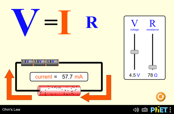
This interactive simulation is the perfect tool to solidify your understanding of Ohm's Law.
Click the "Play" button on the webpage to launch the simulation. Once it's loaded, perform the following two experiments: Experiment 1: The effect of Voltage on Current Set the Resistance (R) slider to a middle value, like 500 Ω. Don't change it for this experiment. Start with the Voltage (V) slider at its minimum value (0.1 V). Note the value of the current (I). Slowly increase the voltage. Watch what happens to the current. As you double the voltage, what happens to the current? You should observe a direct relationship: as voltage increases, current increases proportionally. This is because there is more "pressure" pushing the electrons. Experiment 2: The effect of Resistance on Current Set the Voltage (V) slider to a fixed value, like 4.5 V. Don't change it for this experiment. Start with the Resistance (R) slider at its minimum value (10 Ω). Note the value of the current. Slowly increase the resistance. Watch what happens to the current. As you double the resistance, what happens to the current? You should observe an inverse relationship: as resistance increases, current decreases. This is because there is more "opposition" to the flow of electrons.
This hands-on experience is exactly what engineers and physicists do: they form a hypothesis (e.g., "increasing voltage should increase current") and then test it in a controlled environment.
From Theory to Practice
While the PhET simulation is abstract, these measurements are performed in the real world (and in more detailed simulators) using tools like multimeters. The image below shows a circuit built on a simulated breadboard, which is a prototyping tool. It includes a power supply, a resistor (the small component with colored bands), and two multimeters set up to measure voltage and current.
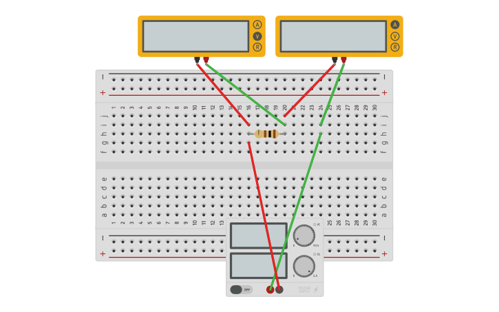
This is a preview of the kind of environment we will be working in when we start building logic gates. We will need to use resistors strategically to ensure the currents and voltages are at the correct levels for our transistors to behave as reliable ON/OFF switches.
Conclusion
In this lesson, we moved from the abstract idea of an electronic switch to the fundamental laws that govern the circuits they inhabit. You now have a practical, visual understanding of the relationship between voltage, current, and resistance.
Here are the key takeaways:
- Voltage is the electrical "pressure" that pushes charge.
- Current is the "flow" of charge.
- Resistance is the "opposition" to that flow.
- Ohm's Law () provides the mathematical relationship that connects them.
- In a circuit with constant resistance, current is directly proportional to voltage.
- In a circuit with constant voltage, current is inversely proportional to resistance.
You've explored these concepts theoretically and, most importantly, visualized them through simulation. With this foundational knowledge of circuit behavior in place, we are now fully prepared for the next exciting step. In the following lesson, we will combine our knowledge of transistors and circuit laws to construct and simulate our very first logic component: a NOT gate.