Hello! Welcome back to our exploration of 3D generative models.
In our last lesson, we surveyed the landscape of 3D data representations. We contrasted explicit formats like voxels, point clouds, and meshes with implicit, function-based representations. We concluded that neural fields—which define geometry as a continuous function—are a particularly powerful and flexible choice for generative modeling.
Today, we will dive deep into the most influential neural field architecture: Neural Radiance Fields (NeRFs). Your learning outcome is to describe NeRFs and their rendering process. We will dissect how a simple neural network can learn to represent a complex 3D scene's geometry and appearance, and then explore the rendering pipeline that turns this implicit representation into a photorealistic 2D image.
This conceptual understanding is the critical foundation for the hands-on implementation work we'll do in the next few lessons and for the advanced text-to-3D techniques we'll tackle later in the course.
1. The Core Idea: A Scene as a Continuous Function
At its heart, NeRF solves the problem of novel view synthesis: generating new images of a scene from arbitrary camera angles, given a sparse set of input images.
Instead of storing geometry explicitly (like in a voxel grid or mesh), NeRF represents a scene using a single, continuous function, typically a Multi-Layer Perceptron (MLP). The key idea is to "overfit" this small network to a single scene, encoding all the scene's information within the network's weights.
This MLP acts as a "radiance field." For any point in 3D space, you can ask the network two questions:
- What color is here?
- How dense/opaque is it here?
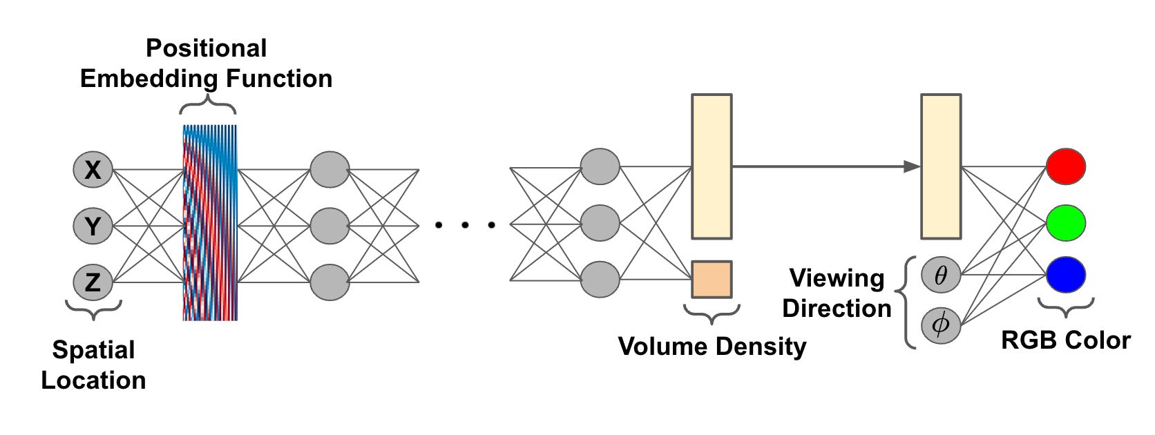
The network takes a 5D coordinate as input—a 3D location and a 2D viewing direction —and outputs a 4D value: an RGB color and a volume density .
This simple but powerful concept is visualized below.

To get a feel for the problem NeRF addresses and its motivation, let's watch a short segment from a presentation by Matthew Tancik, one of the original NeRF authors. He begins by highlighting the limitations of traditional grid-based methods, a topic that should be familiar from our last lesson.
Matthew Tancik: Neural Radiance Fields for View Synthesis
This clip from a talk by NeRF co-author Matthew Tancik introduces the task of view synthesis and motivates the use of a continuous neural representation by contrasting it with the scaling problems of discrete voxel grids.
Watch from 01:11 to 02:35 to understand the view synthesis problem, then from 02:35 to 04:50 for the critique of voxel grids, and finally from 06:41 to 07:20, where he introduces the core idea of NeRF.
2. The NeRF Architecture
The specific design of the NeRF MLP is intentional and crucial for capturing realistic scenes. As mentioned, density () should ideally only be a function of location, while color () can change depending on the viewing angle (e.g., reflections on a shiny surface).
To achieve this, the NeRF architecture processes the inputs in stages:
- The 3D position is passed through a series of MLP layers.
- These layers produce the volume density and an intermediate feature vector.
- The feature vector is then concatenated with the 2D viewing direction .
- This combined vector is passed through additional layers to produce the final RGB color .
This structure ensures that density is view-independent while color can be view-dependent.
3. The "Secret Sauce": Positional Encoding
If you were to implement the MLP as described so far, you would find the results to be disappointingly blurry. Standard MLPs have a "spectral bias," meaning they are inherently better at learning low-frequency functions and struggle to represent the sharp, high-frequency details found in real-world images.
The authors of NeRF overcame this with a clever trick: positional encoding. Before being fed to the network, the continuous input coordinates ( and ) are mapped to a higher-dimensional feature space using a set of sine and cosine functions of varying frequencies.
This isn't the same as positional encoding in Transformers, which encodes discrete positions in a sequence. Here, it helps the MLP to reason about the input coordinates at multiple scales, making it far easier to learn high-frequency variations in color and geometry.
The following segment provides an excellent and intuitive explanation of why this is so effective, using a simple 2D image-fitting task as an example.
Matthew Tancik: Neural Radiance Fields for View Synthesis
This clip from Matthew Tancik's talk demonstrates the critical importance of positional encoding. He shows that a standard MLP fails to represent high-frequency details in a simple 2D image, but succeeds once positional encoding is applied to the input coordinates.
Watch from 28:52 to 30:52. Pay close attention to the visual comparison between the MLP output with and without positional encoding.
Test your understanding!
Imagine you are training a NeRF for a scene containing a matte, non-reflective object (like a clay pot) and a highly reflective object (like a chrome sphere). How would the network use the positional and directional inputs differently to represent these two objects?
Show answer
- For the matte clay pot: The network would learn that the color is almost entirely determined by the spatial location . The viewing direction would have very little influence on the final RGB output for points on the pot's surface. The network weights in the final layers (after the direction is injected) would be small.
- For the chrome sphere: The network would learn a strong dependency on the viewing direction . For a given point on the sphere's surface, the output color would change dramatically with the viewing angle to model the reflections of the surrounding environment. The network weights in the final layers would be large and highly sensitive to changes in .
4. The Rendering Process: From a Field to Pixels
Now that we have a function that represents our scene, how do we use it to create an image? The answer is volume rendering.
The intuition is to simulate the physics of light transport. For each pixel in our target image, we trace a camera ray from the camera origin in the direction through that pixel. The color of the pixel is the accumulated color of all the tiny particles of light that the ray passes through in the scene.
This process is formalized by the volume rendering integral:
Where:
- is the final color for the ray .
- and are the density and color at point along the ray, as predicted by our NeRF MLP.
- is the transmittance, which represents the probability that the ray travels from the near bound to the point without hitting anything. It's the accumulated transparency up to that point. It is defined as:
In practice, we can't compute this continuous integral directly. Instead, we approximate it using a discrete sum, a technique known as numerical quadrature. We sample points along the ray and sum their contributions. The discrete formula, which closely resembles classical alpha compositing from computer graphics, is:
Where:
- is the color of the -th sample.
- is the opacity of the -th sample, where is the distance to the next sample.
- is the discrete transmittance, the probability of reaching the -th sample.
The following reading provides an excellent, mathematically rigorous derivation of these equations, starting from first principles. It also shows how the discrete sum is equivalent to alpha compositing.
NeRF: A Volume Rendering Perspective
This blog post, 'NeRF: A Volume Rendering Perspective', offers a fantastic breakdown of the math behind volume rendering. It's perfect for understanding how the continuous integral is derived and then discretized for implementation.
Read the sections 'The rendering formula' and 'Numerical quadrature'. Focus on understanding the physical intuition behind terms like volume density (σ) and transmittance (T), and how the continuous integral is transformed into the discrete sum used in practice.
The most important takeaway is that this entire rendering process—casting rays, querying the network, and composing the results—is fully differentiable. This means we can use gradient descent to optimize the network's weights by minimizing the difference between the rendered pixel colors and the ground-truth pixel colors from our input images.
5. Efficient Rendering: Sampling Strategies
Naively sampling hundreds of points along every single ray for every pixel in an image would be computationally infeasible. NeRF employs a clever two-pass strategy to make this more efficient.
-
Stratified Sampling (Coarse Pass): Instead of sampling at fixed intervals, the ray is divided into uniform bins, and one sample is drawn randomly from within each bin. This ensures that samples are spread out but also that the continuous volume is more broadly explored during training. These samples are passed through a "coarse" MLP.
-
Importance Sampling (Fine Pass): The outputs from the coarse pass give us a rough idea of where the object's mass is located along the ray (i.e., where the weights are high). A second set of samples is drawn from the ray, this time biased towards these important regions. All samples are then passed through a separate "fine" MLP to compute the final, high-quality pixel color.
This hierarchical volume sampling strategy focuses computational power where it matters most, allowing for higher quality renderings with fewer total samples.
The following short clip explains this two-network approach.
NeRF: Representing Scenes as Neural Radiance Fields for View Synthesis (ML Research Paper Explained)
This clip from Yannic Kilcher's explanation of the NeRF paper provides a clear and concise overview of the hierarchical volume sampling strategy.
Watch from 28:34 to 30:15. Focus on how the 'coarse' network's output is used to intelligently guide the sampling for the 'fine' network.
Conclusion
In this lesson, we have unpacked the core components of Neural Radiance Fields. We've seen how a surprisingly simple MLP, augmented with positional encoding, can represent a complex 3D scene, and how the principles of volume rendering can transform that implicit representation into a photorealistic image.
Key Takeaways:
- A NeRF represents a scene with an MLP that maps a 5D coordinate (3D position + 2D direction) to a 4D output (RGB color + volume density ).
- Positional encoding is a crucial technique that allows the MLP to learn the high-frequency details necessary for photorealism.
- Volume rendering is a differentiable process that synthesizes a pixel's color by integrating the color and density contributions of points sampled along a camera ray.
- The continuous rendering integral is approximated with a discrete sum that is equivalent to alpha compositing.
- Hierarchical sampling makes rendering more efficient by using a coarse-to-fine approach to focus sample points on meaningful areas of the scene.
Next Lesson Preview:
Now that we have a solid conceptual grasp of the NeRF rendering pipeline, we will shift our focus to implementation. The next lessons will be hands-on, where we'll build the key components of this pipeline from scratch. We'll start by implementing ray generation for a pinhole camera model, the very first step in turning a pixel coordinate into a ray ready for marching through our scene.