Introduction
In our last lesson, you learned to identify the three primary low-power modes of your STM32 microcontroller—Sleep, Stop, and Standby—directly from the datasheet. You now understand the fundamental trade-offs between power savings, wake-up time, and state retention for each mode. This theoretical foundation is crucial, but an engineer's true value lies in applying theory to practice.
Today, we will do exactly that. Our goal is to implement interrupt-driven logic to replace polling and enable low-power modes. You will learn one of the most important principles in efficient firmware design: instead of constantly asking the hardware "Are we there yet?", we will let the hardware tell us when something important has happened. This shift in thinking is the key to unlocking the power-saving potential of your MCU.
We will refactor a simple, power-hungry polling application into an efficient, interrupt-driven one that spends most of its time in Sleep mode, waking only when necessary.
1. The Inefficiency of Polling
Let's consider a basic task: toggle an LED when a button is pressed. The most straightforward approach is polling, where you continuously check the button's state inside a while(1) loop.
// Simplified polling example
while (1)
{
    if (HAL_GPIO_ReadPin(BUTTON_PORT, BUTTON_PIN) == GPIO_PIN_RESET)
    {
        HAL_GPIO_TogglePin(LED_PORT, LED_PIN);
        HAL_Delay(200); // Simple debounce
    }
}
While functional, this code is incredibly inefficient from a power perspective. The CPU is running at full speed, executing millions of instructions per second, just to repeatedly check a pin. The vast majority of this activity is wasted, as the button's state changes infrequently.
This diagram perfectly illustrates the difference between polling and an interrupt-driven approach.
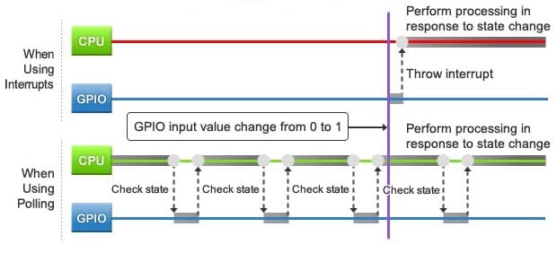
Our goal is to transform our code from the top model (polling) to the bottom model (interrupt-driven), allowing the CPU to enter a low-power state instead of being wastefully "Busy".
2. From Polling to Interrupts: The "Wait For Interrupt" (WFI) Strategy
Instead of polling, we will configure the system to enter a low-power mode and rely on an external interrupt (EXTI) from the button pin to wake it up. The core of this strategy revolves around the "Wait For Interrupt" (WFI) instruction.
When the CPU executes WFI, it halts and enters a low-power state until an interrupt occurs. The STM32 HAL provides a convenient function for this: HAL_PWR_EnterSLEEPMode().
However, there's a critical detail. By default, the SysTick timer generates an interrupt every 1ms to service the HAL time base (HAL_GetTick()). If we simply enter Sleep mode, the SysTick interrupt will wake the CPU up almost immediately, defeating the purpose.
The solution is to temporarily disable the SysTick interrupt before sleeping and re-enable it upon waking.
The following document provides an excellent, in-depth explanation of these concepts.
This guide from Master ESET delves into the specifics of implementing low-power modes. It explains the 'Wait For Interrupt' instruction and the necessity of handling the SysTick timer.
Please read two sections from this PDF to understand the core mechanics: Section 4.1 'WFI instruction: Wait For Interrupt': Focus on section 4.1.1 and the code in 4.1.2. This introduces the HAL_PWR_EnterSLEEPMode() function with the PWR_SLEEPENTRY_WFI parameter and highlights the need to suspend the SysTick. Section 3.11 'Effect of the SysTick interrupt': This section visually and textually explains why the SysTick interrupt prevents effective sleep and introduces the HAL_SuspendTick() and HAL_ResumeTick() functions.
Practical Implementation
Let's see this in action. The process involves configuring a GPIO as an external interrupt, then using the WFI strategy in our main loop.
Sleep & Low Power Modes with STM32
This video from '1s and 0s' provides a practical demonstration of putting the MCU to sleep and waking it with an external interrupt from a button.
Watch the segment from 15:07 to 21:53. Pay close attention to these steps: Configuring the GPIO pin for Interrupt mode (not Event mode for now). The main loop logic: HAL_SuspendTick(), followed by HAL_PWR_EnterSLEEPMode(), and HAL_ResumeTick() after waking. The implementation of the interrupt handler (HAL_GPIO_EXTI_Callback), where the wake-up logic is placed and the interrupt flag is cleared.
To summarize the logic for an interrupt-driven sleep cycle:
- Setup: Configure a GPIO pin (e.g., your button pin) to trigger an external interrupt (EXTI) on a rising or falling edge. Enable the corresponding interrupt in the NVIC.
- Main Loop
while(1):- Print a message like "Entering Sleep Mode..." to your UART terminal.
- Call
HAL_SuspendTick()to prevent the SysTick from waking the CPU. - Call
HAL_PWR_EnterSLEEPMode(PWR_MAINREGULATOR_ON, PWR_SLEEPENTRY_WFI). The code execution will pause here until an interrupt occurs. - (CPU is now asleep)
- ... (Button is pressed, EXTI fires, CPU wakes up) ...
- Execution resumes here, immediately after the sleep function.
- Call
HAL_ResumeTick()to restore the HAL time base. - Print a "Woke up!" message to the UART.
- Interrupt Callback
HAL_GPIO_EXTI_Callback():- This function is automatically called when the EXTI interrupt for your button pin occurs.
- Inside this function, you can perform the immediate action, such as toggling an LED.
- Important: The primary role of the ISR in this design is simply to wake the processor. The main loop handles what to do after waking up.
This design is vastly more power-efficient. The CPU is completely idle, consuming minimal power, until the user provides input.
3. A More Elegant Approach: "Sleep-on-Exit"
For applications that are almost entirely event-driven, there's an even more efficient feature built into the ARM Cortex-M core called Sleep-on-Exit.
When this feature is enabled, the MCU automatically re-enters sleep mode as soon as it finishes executing an Interrupt Service Routine (ISR). It doesn't even return to the while(1) loop. The CPU is only active for the brief period it takes to service the interrupt.
This is perfect for a device that should do nothing but react to external events.
STM32 Low Power Modes: Sleep, Stop, and Standby Explained
The ControllersTech article provides a very clear, concise explanation of the Sleep-on-Exit feature and the HAL functions used to control it.
Please read the subsection titled 'Using SLEEPONEXIT' within the 'STM32 SLEEP MODE' section. It explains the concept and introduces the HAL_PWR_EnableSleepOnExit() function.
Now, let's watch a practical demonstration of this powerful feature.
STM32 Sleep Mode Tutorial | Reduce MCU Power Consumption
The companion video from ControllersTech demonstrates the Sleep-on-Exit feature. Notice how the code in the main loop after the sleep instruction is no longer executed when an interrupt wakes the device.
Watch the segment from 07:35 to 09:44. The key things to observe are: The call to HAL_PWR_EnableSleepOnExit(). The CPU wakes up, executes the callback function (printing a message), and immediately goes back to sleep without running any code from the main while loop. How you might disable the feature (HAL_PWR_DisableSleepOnExit()) inside a specific interrupt if you want that event to fully wake the system and return to the main loop.
The Sleep-on-Exit logic simplifies your main function significantly:
- Setup: During initialization, after setting up your peripherals and interrupts, call
HAL_PWR_EnableSleepOnExit(). - Main Loop
while(1): This loop can now be completely empty! The first time an interrupt occurs, the CPU will execute the ISR and then automatically go to sleep. It will remain asleep, waking only to service subsequent interrupts.
Conclusion
Today you have bridged the gap from theory to practice in power management. You have learned how to transform an inefficient polling-based design into a power-saving, interrupt-driven one by leveraging the MCU's Sleep mode.
Key Takeaways:
- Polling is inefficient: It keeps the CPU busy and consumes significant power for no productive reason.
- Interrupts enable sleep: By configuring peripherals to trigger interrupts, you can let the CPU enter a low-power mode while waiting for an event.
WFI(Wait For Interrupt) is the core instruction for this strategy, implemented in the HAL viaHAL_PWR_EnterSLEEPMode().- The SysTick timer must be suspended (
HAL_SuspendTick()) before entering Sleep mode to prevent it from waking the MCU immediately. - Sleep-on-Exit (
HAL_PWR_EnableSleepOnExit()) is a powerful feature for purely event-driven systems, allowing the MCU to automatically return to sleep after servicing an interrupt.
Preview of the Next Lesson:
You've now successfully implemented Sleep mode. In the next lesson, we will go deeper. You will place the MCU into the more powerful Stop mode and wake it using an EXTI. More importantly, you will finally connect your multimeter to the circuit and measure the current consumption in Run, Sleep, and Stop modes to see the real-world impact of your power optimization efforts.