Hello! Welcome to the next lesson in our journey to master the STM32 microcontroller.
In our previous session, we successfully configured the SysTick timer to create a precise 1ms time base and built a delay_ms() function. This gave us control over the timing of our code. We already know how to control outputs by blinking an LED. Now, it's time to learn how to process inputs from the outside world.
Today's lesson focuses on this learning outcome: Configure GPIO pins for input mode with internal pull-up/pull-down resistors. We will explore why simply connecting a button isn't enough and how to use the microcontroller's internal features to create a reliable digital input.
By the end of this lesson, you will be able to write a bare-metal program that reads the state of a push-button and controls an LED accordingly.
1. The Problem of the Floating Pin
When a GPIO pin is configured as an input but isn't connected to a definite voltage source (like VCC or GND), it's said to be "floating". An unconnected input pin acts like a small antenna, picking up electromagnetic noise from the environment. This noise can cause the voltage at the pin to drift unpredictably, leading the microcontroller to randomly interpret the input as HIGH or LOW. For a system that needs to be reliable—like anything in an automotive context—this is unacceptable.
To understand this concept visually and see the solution, let's watch a short video.
Pull-up and pull-down resistors explained
The video 'Pull-up and pull-down resistors explained' from the Blueprint IoT channel provides an excellent conceptual overview of why floating pins are a problem and how resistors can solve it.
Watch the following two segments: 00:44 - 03:33: This part explains the 'floating' state and demonstrates how a pull-down resistor provides a default LOW state. 03:33 - 04:46: This explains the complementary concept of a pull-up resistor, which provides a default HIGH state. Focus on the concept of providing a default voltage level, not the specific resistor values for now.
As the video explains, a pull-up resistor connects the pin to the HIGH voltage level (VCC), ensuring it reads HIGH by default. A pull-down resistor connects it to GROUND, ensuring it reads LOW by default. When an external device (like a push-button) is activated, it overcomes this gentle "pull" and forces the pin to the opposite state.
2. Internal Pull-Up/Pull-Down Resistors
While you can add these resistors as external components on your circuit board, modern microcontrollers like the STM32 include them right on the silicon die. These internal resistors can be enabled or disabled in software for each pin, which is incredibly convenient and saves cost and board space.

Our strategy will be to use an internal pull-up resistor. We will connect our push-button between the GPIO pin and Ground.
- When the button is NOT pressed: The internal pull-up resistor pulls the pin's voltage to HIGH. The MCU reads a '1'.
- When the button IS pressed: It creates a direct path to Ground, overriding the resistor and pulling the pin's voltage to LOW. The MCU reads a '0'.
3. Register-Level Configuration for Input Mode (STM32F1 Series)
Let's get back to bare-metal programming. To configure a GPIO pin as an input on your STM32F103, you need to modify its corresponding bits in the Port Configuration Registers (GPIOx_CRL for pins 0-7, GPIOx_CRH for pins 8-15).
For each pin, there are 4 configuration bits:
MODE[1:0]: These two bits set the direction (Input, Output).CNF[1:0]: These two bits configure the mode (e.g., Push-Pull, Open-Drain, Analog, Floating, Pull-up/down).
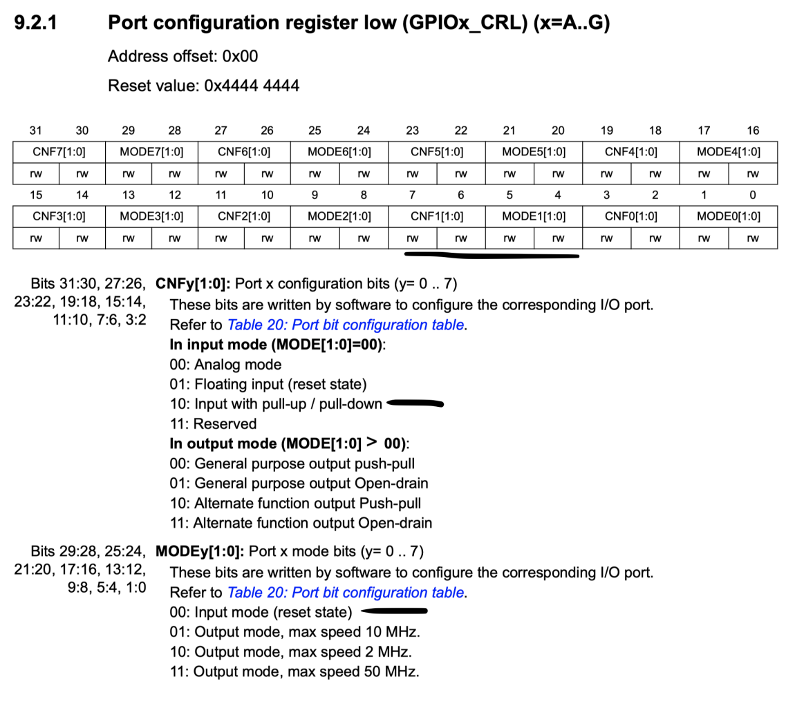
This sets the pin to be an input, but it doesn't specify which pull resistor to use (up or down). On the STM32F1 series, this is done in a unique way: you select between pull-up and pull-down by writing to the corresponding bit in the Port Output Data Register (GPIOx_ODR).
- Writing a
1toODRbitnenables the pull-up resistor for pinn. - Writing a
0toODRbitnenables the pull-down resistor for pinn.
This is a specific detail of the F1 series that often trips up developers accustomed to newer STM32 families, which have a dedicated PUPDR register.
4. Reading the Input Value
Once the pin is configured, its real-time logic level (HIGH or LOW) is available in the Port Input Data Register (GPIOx_IDR). This is a read-only register. To check the state of a single pin, you read the entire IDR and use a bitwise AND operation to isolate the bit you care about.
For example, to read pin 0 of port A (PA0), you would check if bit 0 of GPIOA->IDR is set or cleared.
if ((GPIOA->IDR & (1 << 0)) != 0) {
    // Pin PA0 is HIGH
} else {
    // Pin PA0 is LOW
}
Now, let's see how all these register manipulations come together in a code example.
STM32 GPIO Tutorial (LED and Buttons)- Bare Metal Part 2
The article 'STM32 GPIO Tutorial (LED and Buttons)' from EmbetronicX provides a clear, bare-metal code example for interfacing with a button. We will focus on the code specific to your STM32F103 board.
In the article, scroll down to the 'STM32F1 Code' section. Study the main function carefully. Pay close attention to these lines: GPIOA->CRL &= ~(GPIO_CRL_MODE0|GPIO_CRL_CNF0); and GPIOA->CRL |= GPIO_CRL_CNF0_1;: This is the configuration of PA0 as an input. GPIOA->ODR |= GPIO_IDR_IDR0;: This is the crucial step that enables the internal pull-up resistor. if( ( GPIOA->IDR & GPIO_IDR_IDR0 ) == GPIO_IDR_IDR0 ): This shows how the IDR is read and tested.
5. Hands-On Task: Read a Button, Control an LED
It's time to apply this knowledge. You will now modify your project to read a push-button and use it to control the onboard LED (PC13).
Hardware Setup:
- Connect one leg of a tactile push-button to a GPIO pin, for example, PA0.
- Connect the other leg of the same button to a GND pin on your Blue Pill board.
Software Implementation:
Start with your previous project that has the system clock and SysTick configured.
1. Enable GPIOA Clock:
In your main function, make sure the clock for GPIO Port A is enabled. You already have the clock for Port C enabled for the LED.
// In main.c, inside main() after clock configs

// Enable clock for GPIO Port C (for LED)
RCC->APB2ENR |= (1 << 4); // or RCC_APB2ENR_IOPCEN

// NEW: Enable clock for GPIO Port A (for Button)
RCC->APB2ENR |= (1 << 2); // or RCC_APB2ENR_IOPAEN
2. Configure PC13 as Output (Review):
Ensure PC13 is configured as an output.
// Configure PC13 as General-purpose push-pull output, max speed 50MHz
GPIOC->CRH &= ~((0b11 << 22) | (0b11 << 20)); // Clear CNF13 and MODE13
GPIOC->CRH |=  (0b11 << 20);                  // Set MODE13 to 11 (50MHz)
3. Configure PA0 as Input with Pull-Up:
Now, configure pin PA0 as an input with an internal pull-up resistor. This follows the logic from the Embetronicx article.
// Configure PA0 as Input with pull-up
GPIOA->CRL &= ~((0b11 << 2) | (0b11 << 0)); // Clear CNF0 and MODE0
GPIOA->CRL |=  (0b10 << 2);                 // Set CNF0 to 10 (Input with pull-up/pull-down)
GPIOA->ODR |=  (1 << 0);                    // Set ODR0 to 1 to select pull-up
4. Read Button and Control LED in while loop:
Replace the LED toggling logic in your main while(1) loop. You will now read the button state and set the LED accordingly.
while (1)
{
  // Read the state of the button on PA0
  // Remember: with a pull-up, pressing the button connects it to ground, making the pin LOW.
  if ((GPIOA->IDR & (1 << 0)) == 0)
  {
    // Button is pressed (pin is LOW), turn LED ON.
    // The onboard LED on the Blue Pill is active-low, so we write a 0 to turn it ON.
    GPIOC->ODR &= ~(1 << 13);
  }
  else
  {
    // Button is not pressed (pin is HIGH), turn LED OFF.
    // Writing a 1 turns the LED OFF.
    GPIOC->ODR |= (1 << 13);
  }
}
Compile and flash this code to your board. When you press and hold the button, the onboard LED should light up. When you release it, the LED should turn off.
Conclusion
Congratulations! You have successfully bridged the gap between the physical world and your firmware by reading a digital input. This is a fundamental skill for any embedded systems engineer.
Key Takeaways:
- An unconnected input pin is floating and unreliable.
- Pull-up and pull-down resistors provide a default logic level to prevent floating.
- The STM32 has internal pull resistors that can be configured in software.
- On the STM32F1, you configure a pin for input mode using the
GPIOx_CRxregisters and then select the pull-up/pull-down using theGPIOx_ODRregister. - The state of the physical pin is read from the
GPIOx_IDRregister.
Preview of the Next Lesson:
As you press and release the button, you might see the LED flicker unexpectedly for a brief moment. This is a real-world hardware issue called contact bounce, where the mechanical contacts inside the button bounce several times before settling. In our next lesson, we will investigate this phenomenon and write a software debouncing algorithm to create a clean, reliable button press event.