Hello! Welcome to Module 6.
In our last module, we mastered the art of digital communication with peripherals like I2C LCDs and SPI devices. You learned how to send structured data and, crucially, how to use a logic analyzer to verify that the electrical signals on the bus match your code's intent. This ability to "see" the data is a cornerstone of professional debugging.
Now, we shift our focus from the purely digital realm to the interface between the microcontroller and the analog world. Most sensors—measuring temperature, pressure, light, or distance—produce an analog voltage, not clean digital 1s and 0s. To make sense of this data, we need to convert it into a digital format our CPU can understand.
This lesson introduces the Analog-to-Digital Converter (ADC), the peripheral responsible for this conversion. We'll tackle the first learning outcome of this module: Configure the ADC for single-channel, software-triggered conversions. You will learn how to set up one ADC input, command it to take a single measurement, and read the resulting digital value.
1. From Analog Voltage to Digital Number
An Analog-to-Digital Converter (ADC) is a circuit that converts a continuous analog voltage into a discrete digital value. The precision of this conversion is defined by its resolution.
Your STM32F103C8T6 microcontroller has a 12-bit ADC. This means it can represent an analog voltage range with discrete steps.
- If the input voltage is 0V, the ADC output will be the digital value 0.
- If the input voltage is the reference voltage (typically 3.3V for your board), the ADC output will be the digital value 4095.
- Any voltage in between will be represented by a proportional integer between 0 and 4095.
For a more detailed explanation of this relationship, you can refer to the following article.
ADC Single Channel Single Conversion Mode - EmbeddedExpertIO
The article 'Getting Started with STM32F103: ADC Single Channel Single Conversion Mode' from EmbeddedExpertIO provides a clear, concise explanation of what an ADC is and how to relate its digital output back to an analog voltage. This foundational knowledge is crucial before we begin coding.
Please read sections '1.1 What is the ADC' and '1.2 Relating ADC Value to Voltage'. Focus on understanding the concept of resolution (12-bit) and the simple ratio-metric formula used to correlate the digital output (0-4095) with the input voltage (0-3.3V).
In this lesson, we'll focus on getting that raw digital value (0-4095). In the next lesson, we will use the formula you just read about to convert it into a meaningful physical unit like voltage.
2. Configuring the ADC in STM32CubeIDE
To use the ADC, we first need to configure the peripheral and the associated GPIO pin. We will use STM32CubeIDE's graphical tool for this. We'll set up the ADC in the simplest configuration: single-channel, software-triggered "polling" mode. This means we will use one pin to read one analog signal, and our code will manually start a conversion and then wait (poll) for it to finish.
The video below from ControllersTech provides an excellent walkthrough of the ADC configuration options. While the main demonstration uses a more advanced STM32 chip, the instructor specifically compares the settings to the STM32F103, which is perfect for our needs.
STM32 ADC Tutorial (Part1): Single Channel Polling Mode Explained
Watch this segment of 'STM32 ADC Tutorial (Part1): Single Channel Polling Mode Explained' to understand the key configuration parameters in STM32CubeIDE. This will provide the 'why' behind the settings we choose.
Watch from 04:15 to 07:37. Pay close attention to the explanation of: Resolution: Note how the instructor points out that for the STM32F103, the resolution is fixed at 12-bit (unlike other MCUs). Scan Conversion Mode: We disable this because we are only reading one channel. Continuous Conversion Mode: We disable this because we want to trigger each conversion manually from our software, not have the ADC run continuously. Data Alignment: Right-alignment is standard and makes the 12-bit result easy to read from the 16-bit data register. Sampling Time: A longer sampling time can improve accuracy for signals with high impedance, at the cost of conversion speed. We will start with a default value.
Activity: Configure Your Project
Now, it's your turn. Create a new STM32CubeIDE project for your Blue Pill board and follow these steps to configure the ADC.
- Enable Peripherals:
- In the System Core -> SYS category, set Debug to
Serial Wire. - In the Analog -> ADC1 category, check the box for one of the input channels. For example, check IN0, which will assign pin PA0 as an analog input.
- In the System Core -> SYS category, set Debug to
- Configure ADC1:
- Click on the ADC1 peripheral in the configuration panel.
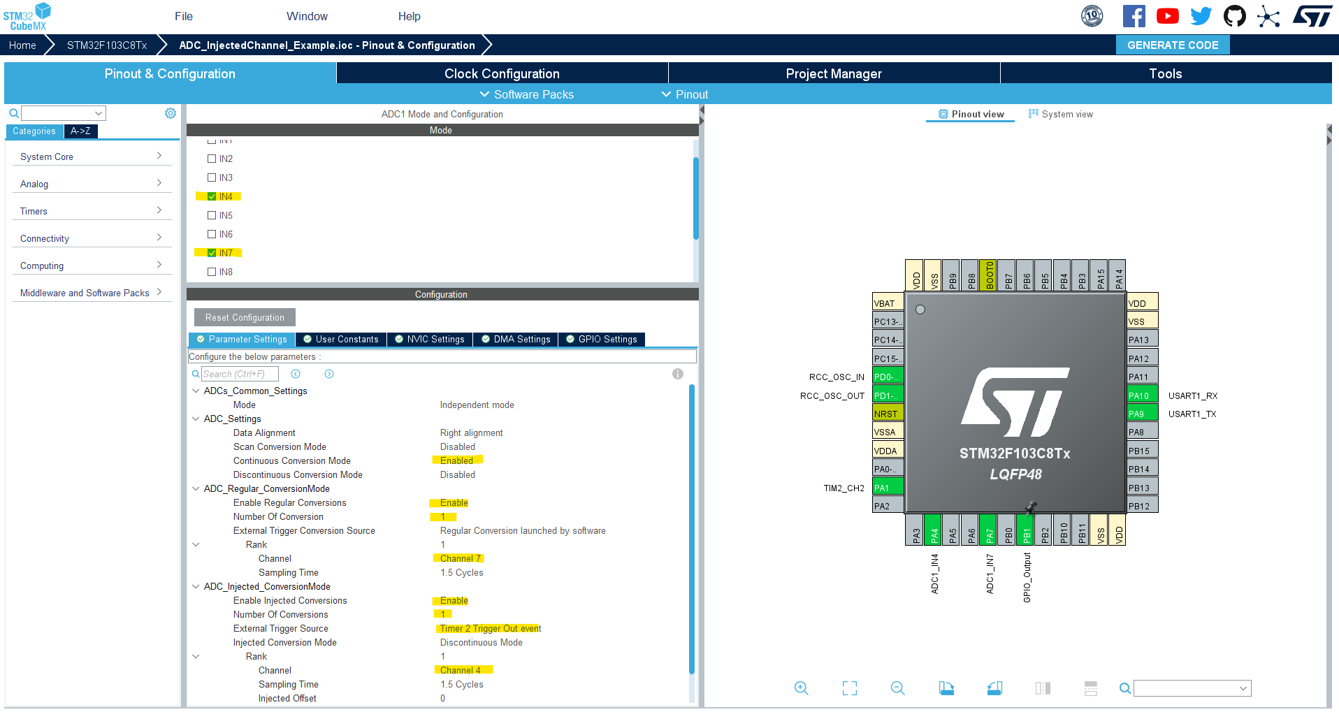
- Verify the settings based on the video you just watched. The most important ones for our single-channel polling mode are:
Data Alignment: Right alignmentScan Conversion Mode: DisableContinuous Conversion Mode: DisableEnd of Conversion Selection: End of single conversion
- Under Regular Conversion Mode, ensure the
External Trigger Conversion Sourceis set to Regular Conversion launched by software. This is the key to our software-triggered approach.
This is what your configuration should look like:
- Generate the code by saving the
.iocfile.
3. Reading the ADC Value with HAL Functions
With the code generated, we can now write the logic in main.c to perform a conversion. The process involves a sequence of four HAL functions that you'll place inside the while(1) loop.
The following article from ControllersTech (the text version of the video you watched) provides the exact code snippet we need.
STM32 ADC Single Channel Polling Mode | HAL & CubeMX Guide
This article, 'STM32 ADC Single Channel Polling Mode', provides a clear code example for performing a software-triggered read. We will use the functions it demonstrates.
Scroll down to the 'The main function' section. Read through the code block and the numbered list explaining the four key HAL functions: HAL_ADC_Start, HAL_ADC_PollForConversion, HAL_ADC_GetValue, and HAL_ADC_Stop.
Here is a summary of the polling sequence:
HAL_ADC_Start(&hadc1);: This function "wakes up" the ADC and starts a single conversion.HAL_ADC_PollForConversion(&hadc1, HAL_MAX_DELAY);: This is a blocking function. The CPU will pause here and wait until the ADC hardware sets its "End of Conversion" (EOC) flag. This is the "polling" step.HAL_ADC_GetValue(&hadc1);: Once the conversion is complete, this function reads the 16-bit data register containing our 12-bit result.HAL_ADC_Stop(&hadc1);: This function can be called to power down the ADC to save energy, though it's optional for this simple test.
While simple, this polling method is inefficient because the CPU is stuck waiting in HAL_ADC_PollForConversion and can't do other work. In future lessons, we will see how interrupts and DMA provide far more efficient solutions.
4. Hands-On Lab: Reading a Potentiometer
Let's put everything together and read a real analog signal.
Hardware Setup
You will need a 10k Ohm potentiometer. Connect it to your Blue Pill board as follows:
- Connect one of the outer pins of the potentiometer to a 3.3V pin on your board.
- Connect the other outer pin to a GND pin.
- Connect the middle pin (the "wiper") to your chosen ADC pin, PA0.
As you turn the potentiometer's knob, the voltage on the middle pin will vary smoothly between 0V and 3.3V, providing a perfect analog input for our test.
Code and Debug
-
In your
main.cfile, declare a variable to hold the ADC result just before thewhile(1)loop:/* USER CODE BEGIN 2 */ uint16_t adc_value; /* USER CODE END 2 */ -
Inside the
while(1)loop, implement the polling sequence:/* USER CODE BEGIN WHILE */ while (1) { HAL_ADC_Start(&hadc1); HAL_ADC_PollForConversion(&hadc1, HAL_MAX_DELAY); adc_value = HAL_ADC_GetValue(&hadc1); HAL_ADC_Stop(&hadc1); HAL_Delay(100); // Wait 100ms before the next reading /* USER CODE END WHILE */ -
Now, let's verify our code using the debugger's "Live Expressions" feature. This powerful tool lets you watch variables change in real-time.
16. STM32CubeIDE Potentiometer ADC with STM32F103C8T6
The following video from MicroPeta demonstrates exactly how to use the debugger to see your ADC value live. It uses your specific STM32F103C8T6 board.
Watch from 01:49 to 05:48. Don't worry about the small differences in their code (they use continuous mode). Focus on the debugging process: Starting the debug session (01:49). Opening the 'Live Expressions' window (03:30). Adding your adc_value variable to the watch list (03:45). Running the code and observing the value change as the potentiometer is turned (04:10).
Follow the process shown in the video. Start a debug session, add your adc_value variable to the Live Expressions window, and run the code. Turn the potentiometer knob. You should see the value in the debugger change in real-time, ranging from a number close to 0 to one close to 4095.
Conclusion
Excellent work! You have successfully configured and read from an ADC channel using the fundamental software-triggered polling method. You have taken an external analog voltage, converted it into a digital number, and verified its value inside the MCU using professional debugging tools.
Key Takeaways:
- The ADC converts an analog voltage into a digital number. For the STM32F103, this is a 12-bit value ranging from 0 to 4095.
- Polling mode uses a
Start -> Poll -> GetValuesequence, which is simple to implement but makes the CPU wait, reducing efficiency. - STM32CubeIDE simplifies the configuration of GPIO pins for analog input and ADC parameters like triggers and conversion modes.
- The debugger's "Live Expressions" view is an invaluable tool for monitoring real-time sensor data without having to use a serial port.
Preview of the Next Lesson:
Getting a raw value from 0-4095 is a great first step, but it's not very useful on its own. In our next lesson, you will learn how to convert this raw ADC digital value into a corresponding physical unit, such as voltage. This will allow you to display meaningful data and make decisions based on real-world measurements. We will then explore the central theme of this module: using the Direct Memory Access (DMA) controller to read the ADC without any CPU intervention.