Introduction
Welcome to the next lesson in our bootloader module. In the previous lesson, you successfully designed a memory map for a complete bootloader-application system. By partitioning the flash memory and configuring the linker scripts, you've laid the architectural groundwork for a field-updatable device.
This lesson builds directly on that foundation. Now that you've reserved a specific memory region for the application, you'll learn how to implement functions to erase and write to the internal flash memory. This is the core mechanical capability that enables a bootloader to install new firmware. It's also a fundamental technique for storing persistent configuration data, a common task in automotive ECUs and other professional embedded products.
By the end of this lesson, you will be able to:
- Understand the physical characteristics of the STM32F103's flash memory.
- Use HAL functions to perform the essential unlock, erase, program, and lock sequence.
- Implement robust C functions to write and read data to and from a specific flash address.
- Verify your flash operations using the debugger.
1. The Nature of Flash Memory
Before writing code, it's crucial to understand the rules of the hardware you're controlling. Flash memory is not like RAM; it has its own distinct characteristics.
Let's begin by reading a short introductory text that covers the most important concepts.
Flash Programming in STM32 using HAL (Erase, Write & Read)
The article 'Flash Programming in STM32 using HAL' from ControllersTech provides a concise overview of flash memory principles. It will introduce you to the concepts of non-volatility, the erase-before-write rule, and the difference between page-based and sector-based flash layouts.
Please read the sections 'Introduction to Flash Programming in STM32', 'What is Flash Memory?', and 'Page-Based vs Sector-Based Flash'. Pay close attention to the characteristics of page-based flash, as that is what our STM32F103C8T6 uses.
As you've just read, there are two golden rules for flash memory:
- Erase-before-write: You cannot directly overwrite existing data. An area must first be erased, which sets all its bits to
1. Only then can you program it by changing selected bits to0. - Block-based operations: Erasing doesn't happen byte-by-byte. It happens in larger chunks. For our STM32F103, the flash is page-based, meaning the smallest erasable unit is a 1 KB page.
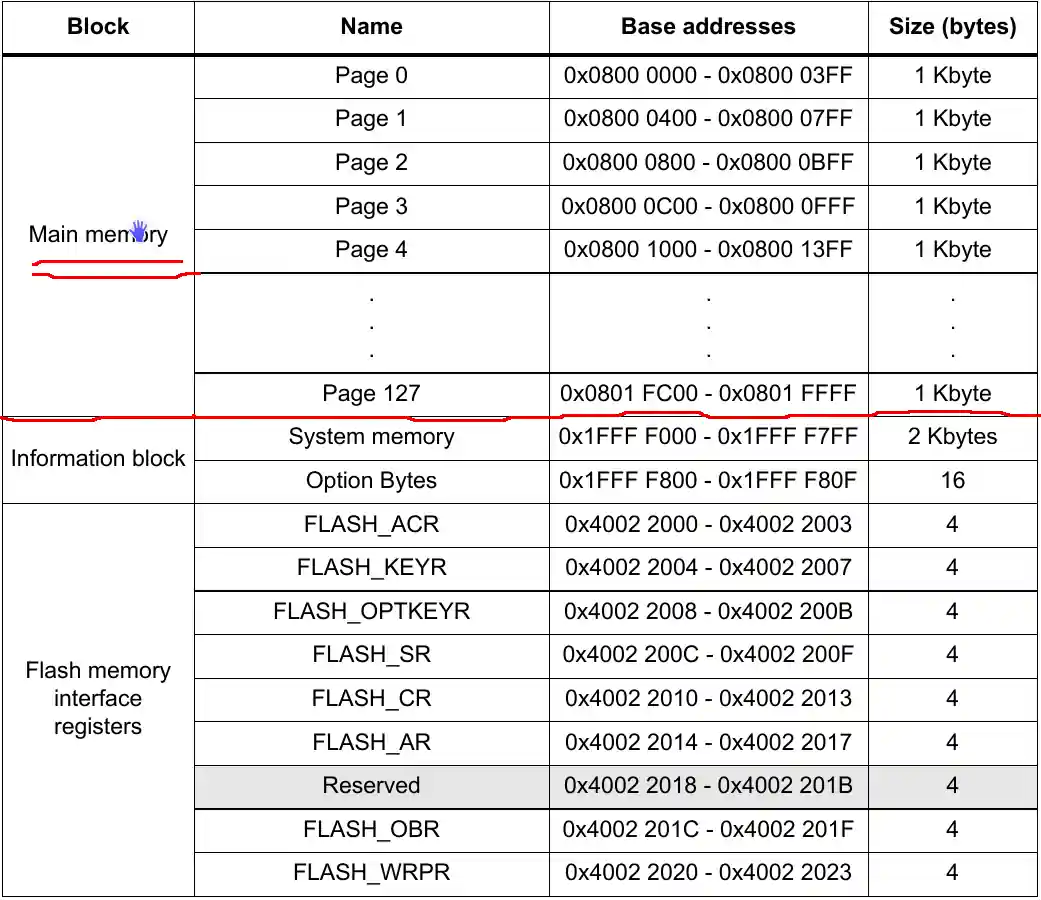
The image below, from the device datasheet, shows this organization. Our 64 KB device has 64 pages of 1 KB each. The hardware that manages these operations is the Flash Program and Erase Controller (FPEC).
2. The Flash Programming Workflow with HAL
To interact with the FPEC, we will use the STM32 HAL library, which simplifies the low-level register manipulations. A complete flash write operation always follows this four-step sequence:
- Unlock the Flash: By default, the FPEC is locked to prevent accidental corruption of the program memory. We must first unlock it.
- Erase the Page(s): Before writing, we must erase the target page(s).
- Program the Data: We write our data, typically in 32-bit words.
- Lock the Flash: Once done, we lock the FPEC again to restore protection.
Let's examine the HAL functions that accomplish this.
Step 1: Unlocking and Locking
These are straightforward function calls:
HAL_FLASH_Unlock();: Unlocks the FPEC. Under the hood, this writes two specific key values (KEY1andKEY2) to theFLASH_KEYRregister.HAL_FLASH_Lock();: Locks the FPEC by setting theLOCKbit in theFLASH_CR(Control Register).
Step 2: Erasing a Page
Erasing is handled by the HAL_FLASHEx_Erase() function. It takes two arguments: a pointer to an initialization structure and a pointer to a variable that will receive any error code.
FLASH_EraseInitTypeDef EraseInitStruct;
uint32_t PageError;

EraseInitStruct.TypeErase   = FLASH_TYPEERASE_PAGES; // We are erasing pages.
EraseInitStruct.PageAddress = 0x08004000;          // Address of the page to start erasing from.
EraseInitStruct.NbPages     = 1;                   // We are erasing one page.

if (HAL_FLASHEx_Erase(&EraseInitStruct, &PageError) != HAL_OK)
{
  // Handle error. PageError will contain the address of the page that failed.
}
This function automates the low-level procedure described in the programming manual (LINK): it sets the Page Erase (PER) bit in FLASH_CR, writes the target address to FLASH_AR, sets the Start (STRT) bit, and then polls the Busy (BSY) bit in FLASH_SR until the operation is complete.
Step 3: Programming Data
Writing data is done with HAL_FLASH_Program(). You must call this function for each word you want to write.
uint32_t targetAddress = 0x08004000;
uint32_t dataWord = 0xDEADBEEF;

if (HAL_FLASH_Program(FLASH_TYPEPROGRAM_WORD, targetAddress, dataWord) != HAL_OK)
{
  // Handle error.
}
This function sets the Programming (PG) bit in FLASH_CR, performs the write to the specified address, and waits for the BSY bit to clear. The STM32F103 hardware writes in 16-bit half-words, but the FLASH_TYPEPROGRAM_WORD option handles the conversion for you.
3. Practical Implementation and Verification
While you can call these HAL functions directly, it's common practice to wrap them in helper functions for convenience. The ControllersTech article provides excellent examples of this.
Flash Programming in STM32 using HAL (Erase, Write & Read)
Let's now look at the practical code. This section of the article provides complete functions, Flash_Write_Data and Flash_Read_Data, that encapsulate the entire workflow.
Read the sections 'STM32 Page-Based Flash memory Programming (STM32F1/M0/M3)' and 'The Main() Function'. Study the implementation of Flash_Write_Data and Flash_Read_Data. Notice how Flash_Write_Data combines the unlock, erase, program, and lock steps.
Your Task: Write and Read from Flash
Now, it's time to apply this in your own project.
-
Create a New Project: For simplicity, create a new, clean STM32CubeIDE project for your Blue Pill board.
-
Add the Helper Functions: Copy the
Flash_Write_DataandFlash_Read_Datafunctions from the article into yourmain.cfile. You will also need a helper functionGetPage()which is not explicitly provided in that section but is simple to create. Here is the full set of functions you'll need:// Helper function to get the page number from an address static uint32_t GetPage(uint32_t Address) { return (Address - FLASH_BASE) / FLASH_PAGE_SIZE; } /* * Note: The following two functions are adapted from the ControllersTech article. * resource_id: [LINK](https://controllerstech.com/flash-programming-in-stm32/) */ uint32_t Flash_Write_Data (uint32_t StartPageAddress, uint32_t *Data, uint16_t numberofwords) { static FLASH_EraseInitTypeDef EraseInitStruct; uint32_t PAGEError; int sofar=0; /* Unlock the Flash to enable the flash control register access *************/ HAL_FLASH_Unlock(); /* Erase the user Flash area */ uint32_t StartPage = GetPage(StartPageAddress); uint32_t EndPageAdress = StartPageAddress + numberofwords*4; uint32_t EndPage = GetPage(EndPageAdress); /* Fill EraseInit structure*/ EraseInitStruct.TypeErase = FLASH_TYPEERASE_PAGES; EraseInitStruct.PageAddress = StartPageAddress; // The article uses StartPage, but PageAddress is correct EraseInitStruct.NbPages = ((EndPage - StartPage) / FLASH_PAGE_SIZE) + 1; if (HAL_FLASHEx_Erase(&EraseInitStruct, &PAGEError) != HAL_OK) { return HAL_FLASH_GetError (); } /* Program the user Flash area word by word */ while (sofar < numberofwords) { if (HAL_FLASH_Program(FLASH_TYPEPROGRAM_WORD, StartPageAddress, Data[sofar]) == HAL_OK) { StartPageAddress += 4; // advance to next word sofar++; } else { /* Error occurred while writing data in Flash memory */ return HAL_FLASH_GetError (); } } /* Lock the Flash to disable the flash control register access */ HAL_FLASH_Lock(); return 0; } void Flash_Read_Data (uint32_t StartPageAddress, uint32_t *RxBuf, uint16_t numberofwords) { while (numberofwords--) { *RxBuf = *(__IO uint32_t *)StartPageAddress; StartPageAddress += 4; RxBuf++; } } -
Use the Functions in
main(): In yourmain()function, define a safe address to write to. Based on our previous lesson's memory map, the metadata region at0x08004000is a perfect candidate./* Inside main() after SystemClock_Config() */ // 1. Define data to write and a buffer for reading uint32_t my_data_to_write[5] = {0x11223344, 0x55667788, 0xAABBCCDD, 0xEEFF0011, 0xCAFEBABE}; uint32_t my_read_buffer[5] = {0}; // Initialize to zero uint16_t num_words = 5; // 2. Define the target flash address // This address is in the 17th KB of flash, safely away from our code. uint32_t flash_address = 0x08004000; // 3. Write the data to flash Flash_Write_Data(flash_address, my_data_to_write, num_words); // 4. Read the data back from flash Flash_Read_Data(flash_address, my_read_buffer, num_words); // 5. Add a breakpoint here to verify __NOP(); // No operation, just a convenient place for a breakpoint. -
Debug and Verify:
- Start a debugging session.
- Open the "Memory" view (
Window > Show View > Memory). - In the Memory view, add a new monitor for the address
0x08004000. - Run the code until it hits the breakpoint at
__NOP(). - Verification 1: Check the Memory view. You should see your data (
11223344, etc.) at the specified address. - Verification 2: Check the "Variables" view. Expand
my_read_buffer. It should now contain the exact same values asmy_data_to_write.
For a visual guide on performing these debugging steps, the following video is very helpful.
STM32 Flash Programming (Page-Wise) on Cortex-M0/M3 | Write & Read with CubeIDE
This video, 'STM32 Flash Programming', demonstrates the entire process, including how to use the debugger's memory tab to verify that the data has been written correctly.
You can watch the segment from 04:16 to 06:37 to see how data is written and verified. Then, watch from 07:27 to 08:56 to see how the read-back process is confirmed in the debugger's live expression window.
4. A Critical Warning: Don't Saw Off the Branch You're Sitting On
What would happen if you mistakenly chose a flash address inside your current program's code area (e.g., 0x08000100)?
The Flash_Write_Data function would first attempt to erase that page. This would wipe out the very instructions the CPU is currently executing! When the CPU tries to fetch its next instruction, it will find only 0xFFFFFFFF (the erased state). This leads to an invalid instruction fetch and an immediate crash into the HardFault_Handler.
The video you just referred to demonstrates this exact scenario. It is a powerful reminder to always be certain of your memory map before performing any flash write operations.
STM32 Flash Programming (Page-Wise) on Cortex-M0/M3 | Write & Read with CubeIDE
To see the consequence of this error, watch this segment from the same video. It provides a memorable demonstration of why memory safety is paramount.
Watch from 08:56 to 10:38.
Conclusion
Congratulations! You have now mastered one of the most fundamental skills in advanced embedded programming: manipulating the internal flash memory. This capability is the linchpin for building bootloaders, storing persistent data, and creating professional, field-updatable products.
Key Takeaways:
- Flash memory on the STM32F1 is page-based (1 KB pages).
- All flash operations require an erase-before-write cycle.
- The standard procedure is Unlock -> Erase -> Program -> Lock.
- The HAL library provides the core functions:
HAL_FLASH_Unlock(),HAL_FLASH_Lock(),HAL_FLASHEx_Erase(), andHAL_FLASH_Program(). - It is critical to choose a safe memory address outside of your running code's region to avoid catastrophic failure.
Preview of the Next Lesson:
You now have all the individual components required to build a bootloader. You can design a memory map, and you can write to flash. In the next lesson, we will integrate these skills to implement a basic bootloader that receives an application binary via UART and programs it into flash.