Hello! Welcome to the final lesson of our module on FreeRTOS.
Over the past few lessons, you've built a solid toolkit of real-time concepts. You've learned to create tasks, pass data between them with queues, synchronize them with events using semaphores, and protect shared resources with mutexes. Now, it's time to put it all together.
This lesson directly addresses the learning outcome: Refactor a polling-based application into a multi-tasked FreeRTOS design. We will take a typical, monolithic "super-loop" application and transform it into a modular, responsive, and scalable RTOS-based system. This is one of the most fundamental skills for a professional embedded systems engineer, moving you from writing linear scripts to designing concurrent systems.
1. The Super-Loop: Simple, but Flawed
Most beginners start with a "super-loop" architecture. The code initializes peripherals and then enters an infinite while(1) loop that continuously polls for events and performs actions.
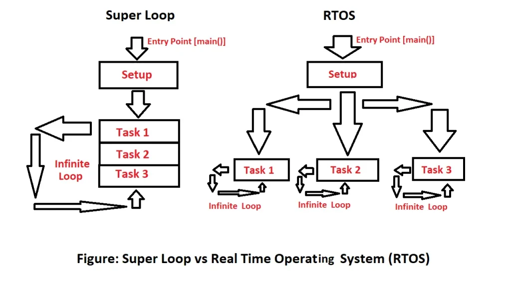
Let's consider a simple polling application that has two main jobs:
- Blink an LED at a steady rate.
- Poll a button and, upon detecting a press, print a message to the UART.
Here is what the main loop for such an application would look like:
// Example polling-based main loop
while (1)
{
    // --- Task 1: Blink an LED every 500ms ---
    // (Non-blocking delay logic using HAL_GetTick())
    static uint32_t last_toggle_time = 0;
    if (HAL_GetTick() - last_toggle_time >= 500)
    {
        HAL_GPIO_TogglePin(LD2_GPIO_Port, LD2_Pin);
        last_toggle_time = HAL_GetTick();
    }

    // --- Task 2: Check for a button press ---
    if (HAL_GPIO_ReadPin(B1_GPIO_Port, B1_Pin) == GPIO_PIN_RESET)
    {
        // This HAL_Delay for debouncing is a huge problem!
        // It blocks the entire system, including the LED blinking.
        HAL_Delay(50);
        if (HAL_GPIO_ReadPin(B1_GPIO_Port, B1_Pin) == GPIO_PIN_RESET)
        {
            printf("Button Pressed!\r\n");
            // Wait until the button is released, blocking everything.
            while(HAL_GPIO_ReadPin(B1_GPIO_Port, B1_Pin) == GPIO_PIN_RESET);
        }
    }
}
This approach has major weaknesses:
- Blocking Operations: The
HAL_Delay()call for button debouncing and thewhileloop waiting for button release will halt the entire system. The LED will stop blinking smoothly. - Poor Responsiveness: The system can only handle one thing at a time. If the button logic were more complex (e.g., involving a long calculation), it would delay the LED blinking and make the system feel unresponsive.
- Lack of Scalability: Adding a third task, like reading a sensor, would require carefully weaving its logic into the loop, making the code tangled and difficult to maintain. The timing of all tasks becomes interdependent.
The following video demonstrates this exact problem, contrasting a simple while loop with an RTOS implementation for blinking LEDs at different rates.
STM32 FreeRTOS Series Part 1: Mastering Tasks & Priorities in STM32CubeIDE
Watch this segment from ControllersTech to see a visual demonstration of how a simple while(1) loop fails to perform two simple timing tasks concurrently, and how FreeRTOS tasks solve this problem effortlessly.
Watch from 06:17 to 09:52. The first part shows the failure of the while loop to generate two signals at different frequencies. The second part shows how two FreeRTOS tasks, each with its own vTaskDelay, can achieve this concurrency perfectly.
2. Designing the Multi-Tasked Architecture
To fix the super-loop, we must break it down into a set of independent, cooperating tasks. The core design process involves:
- Identify Responsibilities: Isolate each unique function of the system (e.g., LED control, button monitoring, data processing, communication). Each of these becomes a candidate for a task.
- Define Task Interactions: Determine how tasks need to communicate or synchronize.
- Does Task A need to send data to Task B? Use a queue.
- Does an ISR need to signal Task C that an event occurred? Use a binary semaphore.
- Do Task D and Task E need to share a peripheral like UART? Protect it with a mutex.
- Assign Priorities: Decide which tasks are more important. A task handling emergency braking in a car is higher priority than one updating the dashboard display.
For our simple example, we can identify three distinct responsibilities:
- Task A: Blinking an LED. This is a simple, periodic background task.
- Task B: Handling the User Button. This should be event-driven and highly responsive.
- Task C: Printing to the UART. This is a communication task that might be used by other tasks in the future.
This leads to the following RTOS-based design:
led_task: A low-priority task that toggles an LED and then blocks usingvTaskDelay().button_handler_task: A medium-priority task that waits for a binary semaphore. The semaphore will be given by the button's EXTI interrupt service routine (ISR). This completely eliminates polling.uart_print_task: A task that waits for messages on a queue. Thebutton_handler_taskwill send a message to this queue when it wants to print something. This decouples the button logic from the UART logic.
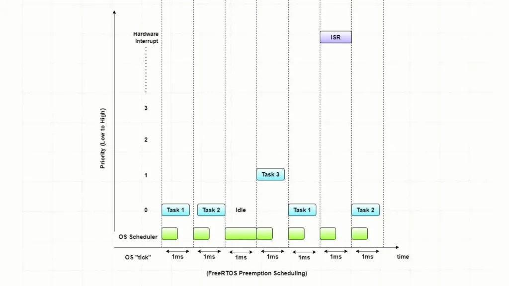
The diagram below illustrates how the FreeRTOS scheduler manages these different tasks, along with interrupts, to create a responsive system.
3. Case Study: A Professional RTOS Design Pattern
Before you implement your own refactoring, let's look at a slightly more complex and professional example. This will show you how these patterns are used in real-world applications. The following tutorial builds an MQTT client with FreeRTOS. Even if you're not familiar with MQTT, focus on the architecture.
The design uses two "producer" tasks that generate data and one "consumer" task that processes it. This is a very common and powerful design pattern.
STM32 ESP8266 MQTT Publish messages with FreeRTOS
This article from ControllersTech demonstrates a clean RTOS architecture. It creates two tasks to generate messages and a third task to handle the transmission of those messages, with a queue connecting them. This is an excellent example of decoupling responsibilities.
Please read through the sections detailing the code implementation. Focus on understanding the 'why' behind the design: "Create MQTT Tasks": Note how there are three tasks with different responsibilities and priorities. "Create MQTT Publish Queue": Understand that a queue is used to pass data from the publisher tasks to the main MQTT task. "Create a structured queue": See how they define a struct to pass complex data (topic and message) in the queue. "Write the Publish Tasks": Observe that these tasks simply prepare a message and send it to the queue using osMessageQueuePut(). "Write the MQTT_Task": Notice that this task's only job is to wait for messages from the queue (osMessageQueueGet()) and handle the shared resource (the MQTT connection).
This case study perfectly illustrates the benefits of an RTOS: the PublishTasks don't need to know anything about how MQTT works, and the MQTT_Task doesn't care where the data comes from. Each part can be developed and tested independently.
4. Hands-On: Refactoring the Super-Loop
Now, let's apply this thinking to refactor the polling code from the beginning of the lesson.
The Goal
Convert the polling-based LED and button application into a three-task, event-driven FreeRTOS application.
led_task: Blinks the onboard LED every 500ms.button_task: Responds to a button press interrupt.print_task: Prints messages received from other tasks over UART.
Step 1: Set up Peripherals and RTOS
- In STM32CubeIDE, ensure your PC13 pin (for the Blue Pill's onboard LED) is set to GPIO_Output.
- Ensure your PA0 pin (or whichever pin your button is connected to) is set to GPIO_Input with a pull-up or pull-down resistor enabled.
- In the GPIO settings for the button pin, set its GPIO mode to
External Interrupt Mode with Rising/Falling edge trigger detection. - In
NVIC Settings, enable the corresponding EXTI line interrupt. - In the
Middlewaresection, enable FreeRTOS (using CMSIS_V2 is fine). Change theSYSTimebase Source to a basic timer likeTIM6to avoid conflicts with the FreeRTOS SysTick.
Step 2: Create RTOS Objects
In main.c, we need handles for our tasks, a queue, and a semaphore.
/* USER CODE BEGIN PV */
// Task Handles
TaskHandle_t ledTaskHandle;
TaskHandle_t buttonTaskHandle;
TaskHandle_t printTaskHandle;

// Queue Handle
QueueHandle_t printQueue;

// Semaphore Handle
SemaphoreHandle_t buttonSemaphore;
/* USER CODE END PV */
In main() before the scheduler starts, create these objects.
/* USER CODE BEGIN 2 */
// Create the print queue to hold up to 5 string pointers
printQueue = xQueueCreate(5, sizeof(char*));

// Create the binary semaphore for the button
buttonSemaphore = xSemaphoreCreateBinary();

// Create the tasks
xTaskCreate(led_task, "LED Task", 128, NULL, 1, &ledTaskHandle);
xTaskCreate(button_task, "Button Task", 128, NULL, 2, &buttonTaskHandle);
xTaskCreate(print_task, "Print Task", 128, NULL, 2, &printTaskHandle);
/* USER CODE END 2 */
Note: Make sure your project's printf is redirected to UART.
Step 3: Implement the Tasks
Now, let's write the logic for each task function.
The LED Task (Simple periodic task)
This task is straightforward. It toggles the LED and delays for 500ms, yielding the CPU to other tasks during the delay.
void led_task(void *pvParameters)
{
    while(1)
    {
        HAL_GPIO_TogglePin(GPIOC, GPIO_PIN_13);
        vTaskDelay(pdMS_TO_TICKS(500));
    }
}
The Print Task (Queue consumer)
This task blocks indefinitely, waiting for a message to appear on printQueue. When it receives a pointer to a string, it prints it.
void print_task(void *pvParameters)
{
    char* messageToPrint;
    while(1)
    {
        // Wait forever for a message to arrive in the queue
        if(xQueueReceive(printQueue, &messageToPrint, portMAX_DELAY) == pdPASS)
        {
            printf("%s", messageToPrint);
        }
    }
}
The Button Task (Event-driven semaphore consumer)
This is the heart of our event-driven design. It waits for the buttonSemaphore, which will be given by an ISR. Once woken, it handles the debounce logic and sends a message to the print_task.
void button_task(void *pvParameters)
{
    char* msg = "Button was pressed!\r\n";
    while(1)
    {
        // Wait forever for the semaphore to be given by the ISR
        if(xSemaphoreTake(buttonSemaphore, portMAX_DELAY) == pdTRUE)
        {
            // --- Debounce Logic ---
            // Small delay to allow the button contacts to settle
            vTaskDelay(pdMS_TO_TICKS(50));
            // Check if the button is still pressed
            if (HAL_GPIO_ReadPin(GPIOA, GPIO_PIN_0) == GPIO_PIN_RESET)
            {
                // Send the message string pointer to the print queue
                xQueueSend(printQueue, &msg, portMAX_DELAY);
            }
        }
    }
}
Step 4: Implement the Interrupt Service Routine (ISR)
Finally, we need to connect the hardware interrupt to our RTOS. In stm32f1xx_it.c, find the HAL_GPIO_EXTI_Callback function. This is where you will give the semaphore.
// In stm32f1xx_it.c
/* USER CODE BEGIN EXTI_IRQ_HANDLER */
// You may need to declare the semaphore handle as 'extern'
extern SemaphoreHandle_t buttonSemaphore;
/* USER CODE END EXTI_IRQ_HANDLER */

void HAL_GPIO_EXTI_Callback(uint16_t GPIO_Pin)
{
  if(GPIO_Pin == GPIO_PIN_0) // Check if the interrupt is from our button pin
  {
    BaseType_t xHigherPriorityTaskWoken = pdFALSE;
    // Give the semaphore from the ISR
    xSemaphoreGiveFromISR(buttonSemaphore, &xHigherPriorityTaskWoken);
    // Yield to a higher priority task if one was woken
    portYIELD_FROM_ISR(xHigherPriorityTaskWoken);
  }
}
Flash this code to your board. You should see the LED blinking steadily. When you press the button, the "Button was pressed!" message appears instantly on your serial terminal, and the LED's blinking is completely unaffected. You have successfully refactored a brittle, polling system into a robust, event-driven, multi-tasked one.
Conclusion
Congratulations on completing the FreeRTOS module! You've gone from basic tasks to designing and implementing a complete multi-tasked application. This process of identifying responsibilities and decoupling them with RTOS primitives is central to modern embedded software development.
Key Takeaways:
- Polling-based "super-loop" architectures are simple but suffer from being brittle, unresponsive, and hard to scale.
- Refactoring to an RTOS design involves breaking the system into independent tasks, each with a single responsibility.
- RTOS primitives are the "glue" that connects these tasks:
vTaskDelay/vTaskDelayUntilfor timing.- Semaphores to signal events from ISRs to tasks.
- Queues to pass data between tasks.
- Mutexes to protect shared resources.
- This decoupled, event-driven architecture is more modular, responsive, and maintainable.
In our next module, we will dive into a topic highly relevant to your automotive goals: the CAN protocol. You will see that a robust CAN communication stack is almost always built using an RTOS, often with dedicated tasks for receiving and transmitting CAN messages—a perfect application for the skills you've just mastered.