Hello! Welcome to the next lesson in our module on Advanced Timers, PWM, and Signal Measurement.
In our last two lessons, you mastered using timers to generate signals. You configured a timer to produce a precise PWM waveform and then learned to dynamically change its duty cycle to create a "breathing" LED effect. Today, we'll explore the other side of the timer's capabilities: using it to measure incoming signals.
Our learning outcome is to configure a timer channel in Input Capture mode. This powerful feature allows the hardware to automatically record the exact time an event occurs on an input pin, forming the foundation for measuring frequency, decoding protocols, and reading data from many sensors, including the ultrasonic sensor in your kit.
1. What is Input Capture?
At its core, Input Capture mode turns a timer channel into a high-precision digital stopwatch. When a specific event (like a signal changing from low to high) occurs on a GPIO pin, the timer hardware instantly saves the current value of its counter into a dedicated register called the Capture/Compare Register (CCR).
This process happens automatically in the hardware, independent of the CPU. It is extremely precise and allows us to measure high-speed signals without the inaccuracies and CPU load associated with software-based polling.
To get a clear mental model of this process, let's start with a short conceptual overview.
How to use Timer Input Capture Mode in STM32
The article 'How to use Timer Input Capture Mode in STM32' from ControllersTech provides an excellent written introduction to the topic. It explains what Input Capture is and why it's superior to software methods.
Please read the section titled 'Introduction to STM32 Input Capture'. Focus on the step-by-step description of how the process works and the key advantages listed.
The process described in the article can be visualized with this diagram:

To see this concept explained with animation, the following video from Fastbit Embedded Brain Academy is very effective.
STM32 General Purpose Timer : Understanding Input Capture (IC) Mode -2
This video provides a clear, animated explanation of how the timer's counter value is captured into the CCR upon a signal's rising edge.
Watch the video from the beginning to 04:17. Pay close attention to the visual of the counter ticking and its value being copied to the capture register when the input signal's rising edge occurs. This will solidify your understanding of the mechanism.
2. A Practical Test Setup
To reliably test our Input Capture configuration, we need a known signal to measure. The best way to do this is to use one timer to generate a PWM signal and another to measure it, all on the same chip. This removes any issues with external wiring or noisy signal sources.
We will configure:
- Timer 1, Channel 1 (TIM1_CH1) on pin PA8 to output a 1kHz PWM signal.
- Timer 2, Channel 1 (TIM2_CH1) on pin PA0 to be in Input Capture mode.
You will need to connect a single jumper wire between pin PA8 and pin PA0 on your Blue Pill board.
3. Bare-Metal Configuration
As with our previous lessons, we will configure the peripherals by directly manipulating their registers. This ensures you understand exactly what the hardware is doing.
Here are the key registers for configuring TIM2_CH1 (on pin PA0) in Input Capture mode:
-
RCC (Reset and Clock Control):
- Enable the clock for
GPIOA(APB2ENR). - Enable the clock for
TIM2(APB1ENR).
- Enable the clock for
-
GPIO (General Purpose I/O):
- Configure
PA0as an input. A floating input (CNF=01,MODE=00) is suitable for this internal loopback test.
- Configure
-
TIM2_CCMR1 (Capture/Compare Mode Register 1): This is the most important register for this task.
CC1S(Capture/Compare 1 Selection) bits: These bits determine if the channel is an output or an input. To configure channel 1 as an input, we setCC1S = 01. This maps the channel to the timer inputTI1.IC1F(Input Capture 1 Filter) bits: These can be used to filter out noise on the input signal. For our clean PWM signal, we'll leave this at0000(no filter).
-
TIM2_CCER (Capture/Compare Enable Register):
CC1P(Capture/Compare 1 Polarity) bit: This determines which edge triggers the capture.0= rising edge,1= falling edge. We'll start by capturing the rising edge.CC1E(Capture/Compare 1 Enable) bit: This must be set to1to enable the capture function for channel 1.
-
TIM2_DIER (DMA/Interrupt Enable Register):
CC1IE(Capture/Compare 1 Interrupt Enable) bit: We set this to1to generate an interrupt every time a capture event occurs on channel 1.
-
TIM2_CR1 (Control Register 1):
CEN(Counter Enable) bit: Set to1to start the timer.
4. Hands-On Lab: Detecting an Edge
Let's apply this knowledge. Your task is to write a program that uses Input Capture to detect the rising edge of a PWM signal and toggle the onboard LED (PC13) in response.
Goal: Configure TIM1_CH1 to generate a 1kHz PWM signal and TIM2_CH1 to capture its rising edges. Each time an edge is captured, toggle the onboard LED.
Steps:
- Create a new project in your STM32CubeIDE workspace.
- In your
main.c, write a function to configureTIM1_CH1(on PA8) to output a 1kHz, 50% duty cycle PWM signal. You can reuse the code from our previous lessons. - Write a function to configure
TIM2_CH1(on PA0) for Input Capture on the rising edge, enabling the capture interrupt. - Configure the onboard LED pin (
PC13) as a push-pull output. - Enable the
TIM2interrupt in the NVIC. - Implement the
TIM2_IRQHandler()function. Inside it:- Check if the interrupt was triggered by a Channel 1 capture event (
TIM_SR_CC1IF). - Crucially, clear the interrupt flag by writing
0to it (TIM2->SR &= ~TIM_SR_CC1IF;). If you don't do this, the ISR will execute forever. - Toggle the state of the PC13 pin.
- Check if the interrupt was triggered by a Channel 1 capture event (
- In
main(), initialize all peripherals and start the timers. - Connect a jumper wire from PA8 to PA0.
- Compile, flash, and run the code.
Expected Result: The PWM signal is 1kHz, so you are generating 1000 rising edges per second. The TIM2_IRQHandler will be called 1000 times per second. Since you toggle the LED in the ISR, the LED's state will change 1000 times per second, causing it to blink at a frequency of 500 Hz. This will appear as a dimly lit, but stable, LED. This confirms your Input Capture setup is working correctly!
Here is the complete solution. Try to implement it yourself first, then use this code as a reference.
#include "stm32f10x.h"

// --- Configuration for PWM Output on TIM1_CH1 (PA8) ---
void pwm_output_init(void) {
    // 1. Enable clocks for GPIOA and TIM1
    RCC->APB2ENR |= RCC_APB2ENR_IOPAEN | RCC_APB2ENR_TIM1EN;

    // 2. Configure PA8 as Alternate Function Push-Pull
    GPIOA->CRH &= ~GPIO_CRH_CNF8_0;
    GPIOA->CRH |= GPIO_CRH_CNF8_1 | GPIO_CRH_MODE8; // AF Push-pull, 50MHz

    // 3. Configure TIM1 base for 1kHz PWM
    // SystemCoreClock is 72MHz. TIM1 is on APB2.
    TIM1->PSC = 71;   // 72,000,000 / (71 + 1) = 1,000,000 Hz
    TIM1->ARR = 999;  // 1,000,000 / (999 + 1) = 1 kHz

    // 4. Configure TIM1 CH1 for PWM Mode 1
    TIM1->CCMR1 |= TIM_CCMR1_OC1M_2 | TIM_CCMR1_OC1M_1; // PWM Mode 1
    TIM1->CCMR1 |= TIM_CCMR1_OC1PE; // Enable preload

    // 50% duty cycle
    TIM1->CCR1 = 500;

    // 5. Enable Channel 1 output
    TIM1->CCER |= TIM_CCER_CC1E;

    // 6. IMPORTANT: Main Output Enable for Advanced Timers like TIM1
    TIM1->BDTR |= TIM_BDTR_MOE;

    // 7. Enable counter
    TIM1->CR1 |= TIM_CR1_CEN;
}

// --- Configuration for Input Capture on TIM2_CH1 (PA0) ---
void input_capture_init(void) {
    // 1. Enable clocks for GPIOA and TIM2
    RCC->APB2ENR |= RCC_APB2ENR_IOPAEN;
    RCC->APB1ENR |= RCC_APB1ENR_TIM2EN;

    // 2. Configure PA0 as input floating
    GPIOA->CRL &= ~(GPIO_CRL_MODE0 | GPIO_CRL_CNF0_1);
    GPIOA->CRL |= GPIO_CRL_CNF0_0;

    // 3. Configure TIM2 base (just set a prescaler to slow it down)
    // TIM2 is on APB1, running at 72MHz (if APB1 prescaler is 1)
    // Let's run the timer counter at 1MHz for easy calculations later
    TIM2->PSC = 71;
    TIM2->ARR = 0xFFFF; // Let it count up to max for a 16-bit timer

    // 4. Configure TIM2 CH1 for Input Capture
    // Clear CC1S bits and then set to '01' for input on TI1
    TIM2->CCMR1 = (TIM2->CCMR1 & ~TIM_CCMR1_CC1S_Msk) | TIM_CCMR1_CC1S_0;

    // 5. Set polarity to rising edge (CC1P=0, default) and enable capture
    TIM2->CCER &= ~TIM_CCER_CC1P;
    TIM2->CCER |= TIM_CCER_CC1E;

    // 6. Enable Capture/Compare 1 interrupt
    TIM2->DIER |= TIM_DIER_CC1IE;

    // 7. Enable TIM2 interrupt in NVIC
    NVIC_EnableIRQ(TIM2_IRQn);

    // 8. Enable TIM2 counter
    TIM2->CR1 |= TIM_CR1_CEN;
}

// --- Onboard LED Configuration (PC13) ---
void led_init(void) {
    RCC->APB2ENR |= RCC_APB2ENR_IOPCEN;
    GPIOC->CRH &= ~(GPIO_CRH_CNF13 | GPIO_CRH_MODE13);
    GPIOC->CRH |= GPIO_CRH_MODE13_0; // Output mode 10MHz
}

// --- TIM2 Interrupt Service Routine ---
void TIM2_IRQHandler(void) {
    // Check if the interrupt is from Channel 1 Capture
    if (TIM2->SR & TIM_SR_CC1IF) {
        // Toggle the onboard LED (PC13)
        // ODR is the Output Data Register
        GPIOC->ODR ^= (1 << 13);

        // IMPORTANT: Clear the interrupt flag
        TIM2->SR &= ~TIM_SR_CC1IF;
    }
}

int main(void) {
    // Set initial state of LED (On is logic low for PC13)
    led_init();
    GPIOC->BSRR = (1 << 13); // Turn LED off initially

    pwm_output_init();
    input_capture_init();

    while(1) {
        // All work is done in the ISR
    }
}
5. The STM32CubeIDE Equivalent
While bare-metal configuration gives you fundamental knowledge, in a professional setting, you'll often use tools like STM32CubeIDE to speed up initialization. The registers you just manipulated correspond directly to settings in the graphical interface.
To achieve the same Input Capture setup in CubeMX:
- Go to Timers -> TIM2.
- Set Channel1 to Input Capture direct mode.
- In the Parameter Settings tab below, you would set:
- Prescaler (PSC): 71
- Counter Period (ARR): 65535
- Polarity Selection: Rising Edge
- In the NVIC Settings tab, check the box to enable the
TIM2 global interrupt.
This graphical approach is faster but performs the exact same register writes you just did by hand.
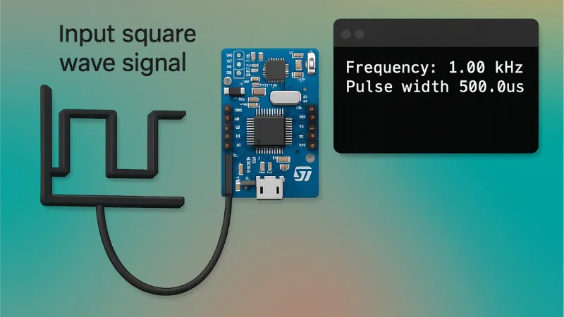
Conclusion
Congratulations! You have successfully configured a timer channel to capture an external event. This is a critical building block for many embedded applications.
Key Takeaways:
- Input Capture uses timer hardware to precisely timestamp incoming signal edges by storing the counter value in the
CCRregister. - The
CCMRxregister'sCCxSbits are used to switch a channel from its default output mode to an input mode. - The
CCERregister'sCCxPandCCxNPbits control the edge polarity (rising, falling, or both). - The
DIERregister'sCCxIEbit enables the interrupt for a capture event, allowing the CPU to process the captured data. - Always remember to clear the interrupt flag in the ISR to prevent re-entry.
Preview of the Next Lesson:
Today, we confirmed that we can detect an edge. In our next lesson, we will use timer Input Capture to measure the pulse width of an external signal. We will read the value from the CCR inside the ISR and perform calculations to determine the exact duration of a pulse. This will prepare you to interface with your HC-SR04 ultrasonic sensor, which reports distance via the width of its echo pulse.