Welcome back! In our previous lesson, we established a solid theoretical foundation for the Controller Area Network (CAN) protocol. You learned about its architecture, the elegant process of bit-wise arbitration, the structure of a data frame, and the robust error-handling mechanisms that make it an automotive industry standard. We also made a crucial distinction between the CAN controller (the logic inside your STM32) and the CAN transceiver (the physical layer IC).
Today, we move from theory to practice. This lesson is all about bridging the gap between the digital world of the microcontroller and the physical world of the CAN bus. Our learning outcome is to connect and configure a CAN transceiver with the STM32. By the end of this lesson, you will have physically wired your TJA1050 CAN transceiver to your STM32F103C8T6 board and configured the necessary pins and peripherals in STM32CubeIDE. This is the essential first step before we can send or receive any data.
1. The Physical Connection: Wiring the CAN Transceiver
The CAN controller in your STM32 operates with logic-level signals (typically 0V and 3.3V). However, the CAN bus itself uses differential signaling, where the voltage difference between two wires (CAN High and CAN Low) determines the logic state. The job of the CAN transceiver is to be the translator between these two domains.
Your kit includes a TJA1050 transceiver module. We will now connect it to your STM32 "Blue Pill" board.
The resource below provides an excellent step-by-step guide for these connections. Although it mentions the MCP2551 transceiver, the pin names and connections are functionally identical for your TJA1050 module.
Please read the following section from the ControllersTech article, which details the wiring between an STM32 and a CAN transceiver. This is the core of our physical setup.
Read the section titled "STM32 MCP2551 Wiring Diagram". Pay close attention to the table showing which STM32 pins connect to the transceiver's pins (TXD, RXD, VDD, VSS) and how the transceiver connects to the bus (CANH, CANL).
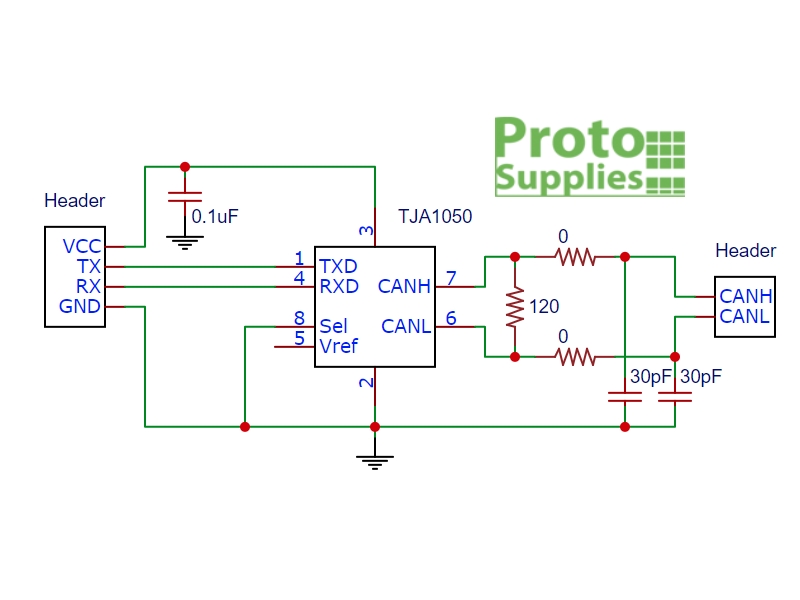
To summarize and visualize the connections for your specific setup:
STM32 to TJA1050 Transceiver Module:
- 5V on STM32 -> VCC or VDD on the transceiver module. (Note: The TJA1050 specifically requires a 5V supply).
- GND on STM32 -> GND or VSS on the transceiver module.
- STM32 CAN TX pin -> TXD on the transceiver module.
- STM32 CAN RX pin -> RXD on the transceiver module.
A Critical Detail: The TX/RX Crossover
A very common mistake is connecting the microcontroller's TX pin to the transceiver's TX pin. Remember their roles:
- The microcontroller Transmits data on its
TXpin. - The transceiver needs to Receive this data to put it on the bus. Its input pin is often labeled
RXD(Receive Data) or sometimesTXD(Transmit Data, referring to the data to be transmitted on the bus).
The golden rule is: The MCU's output (TX) must connect to the transceiver's input, and the transceiver's output must connect to the MCU's input (RX). While the labeling can be confusing, the signal flow is always MCU TX -> Transceiver Input and Transceiver Output -> MCU RX. The article you just read correctly states STM32 PA12 (CAN_TX) connects to the transceiver's TXD pin. This is because on many transceiver modules, the TXD pin is the input from the controller. Always verify with your module's datasheet, but this is the standard convention.
One user on Stack Exchange made this exact mistake, which is a great learning opportunity. Their experience highlights why understanding signal flow is more important than just matching pin names.
Answer to: STM32 HAL_CAN_Transmit always returns TIMEOUT
This short answer on Stack Exchange points out the TX/RX wiring confusion. It's a quick read that reinforces the concept.
Read the second answer on the page (by user 'Tjaart van aswegen'). It's a concise explanation of the TX/RX swap.
Bus Connections and Termination:
- Connect the
CANHpin of your transceiver module to theCANHpin of the other CAN device (or your CAN analyzer). - Connect the
CANLpin to theCANLpin of the other device. - Crucially, ensure a 120Ω termination resistor is connected across the CANH and CANL lines at both ends of the bus. Many transceiver modules have this resistor on-board, sometimes selectable with a jumper. If not, you must add it externally. This resistor prevents signal reflections and is mandatory for a stable CAN bus.
2. Configuring the CAN Peripheral in STM32CubeIDE
With the physical wiring complete, the next step is to configure the STM32's internal CAN peripheral. We will use STM32CubeIDE to enable the CAN peripheral and assign it to the correct physical pins.
The following video provides a clear, step-by-step walkthrough for your exact STM32F103C8T6 microcontroller.
115. STM32CubeIDE MCP2551 CAN BUS with STM32 F103C8T6
This video by MicroPeta will guide you through the STM32CubeIDE configuration. We will follow the setup for one of the two boards shown.
Watch the section from 02:29 to 04:30. Follow these steps in your own STM32CubeIDE project: Start a new project for the STM32F103C8. Enable the Serial Wire Debug (SYS -> Debug -> Serial Wire). Enable the High Speed Clock (RCC -> HSE -> Crystal/Ceramic Resonator). Navigate to Connectivity -> CAN and Activate it. In the pinout view, you'll see that PA11 and PA12 are now green (assigned to CAN). However, for the Blue Pill, these pins are often used for USB. We will remap CAN to different pins. In the CAN "Mode and Configuration" panel, find the PB8_PB9 option in the GPIO dropdown to remap CAN_RX to PB8 and CAN_TX to PB9. Note: We will configure the bit rate and other parameters in the next lesson. For now, our focus is only on activating the peripheral and setting the correct pins.
Let's review the key configuration steps:
- Activate CAN Peripheral: In the
Connectivitytab, selectingCANand clickingActivatedtells CubeMX to generate the initialization code for this peripheral. - Pin Remapping: For the STM32F103, the default CAN1 pins (
PA11,PA12) conflict with the USB peripheral. Remapping toPB8(CAN_RX) andPB9(CAN_TX) is the standard solution for boards like the Blue Pill. You have now instructed the microcontroller to use these specific physical pins for CAN communication.
Here is a visual reference of a completed CAN configuration in CubeMX. While the pins might differ slightly (this image shows PA11/12), the panel and parameter sections are what you will be working with.
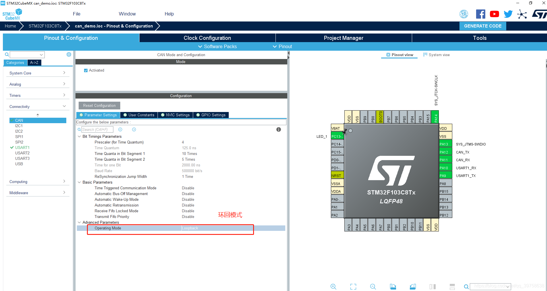
After completing these steps, you can generate the code (Alt+K or Project -> Generate Code). If you inspect the generated main.c file, you will find a function MX_CAN_Init(), which contains the HAL code that configures the peripheral according to the settings you just chose.
Conclusion
Congratulations! You have successfully completed the hardware and initial software setup for CAN communication. This is a foundational skill for any embedded engineer working with modern communication protocols.
Key Takeaways:
- A CAN transceiver (like the TJA1050) is the essential physical layer device that translates between the MCU's logic levels and the CAN bus's differential signals.
- Correct wiring is critical:
MCU TX -> Transceiver RXD,MCU RX -> Transceiver TXD, and a sharedGND. Power must match the transceiver's requirements (5V for TJA1050). - A 120Ω termination resistor is mandatory at each end of the CAN bus to ensure signal integrity.
- In STM32CubeIDE, the CAN peripheral must be activated, and its GPIO pins must be assigned correctly (e.g., remapped to
PB8/PB9on the STM32F103C8T6 to avoid conflicts).
You have laid the physical and firmware groundwork. However, the CAN peripheral is not yet ready to communicate. It doesn't know what speed the bus is running at. In our next lesson, we will address this by learning how to calculate and configure CAN bit timing registers for a specific bus speed. This is a critical step to ensure all nodes on a CAN network can understand each other.