Introduction
Welcome back to our capstone project. In the last lesson, you successfully implemented the TemperatureTask, an efficient FreeRTOS task that periodically reads the MCU's internal temperature using ADC and DMA. The task was synchronized with the hardware using a binary semaphore and currently prints the result to the UART console.
Today, we will take a major step towards creating a true automotive sensor node. Our goal is to implement a second task that packages this sensor data into a CAN message and transmits it. This involves two core embedded engineering concepts:
- Inter-task communication: We need a safe and efficient way to pass the temperature data from the
TemperatureTaskto our new CAN transmission task. - CAN Message Framing: We will construct a standard CAN message, populating it with a specific ID and our sensor data, ready for broadcast on the bus.
This lesson directly addresses two learning outcomes from our project plan: implementing the CAN transmission task and using a FreeRTOS queue to pass data between tasks. By the end, you'll have a task that reads a sensor and another that transmits its data over a CAN bus—a fundamental pattern in distributed embedded systems.
1. Inter-Task Communication: Using a FreeRTOS Queue
In our current design, the TemperatureTask holds the temperature data. Our new CanTxTask needs that data. A naive approach might use a global variable, but this is prone to race conditions and is not a scalable or safe practice in a multi-threaded RTOS environment.
The professional solution is to use a FreeRTOS queue. A queue is a thread-safe data structure that allows tasks and ISRs to send and receive data without needing to worry about concurrent access. It perfectly decouples the data producer (TemperatureTask) from the data consumer (CanTxTask).
Let's modify our existing code to incorporate a queue.
1.1. Create the Queue
First, declare a handle for the queue in the USER CODE BEGIN PV section of main.c. Then, create the queue itself in main() before the scheduler starts.
/* Private variables ---------------------------------------------------------*/
/* USER CODE BEGIN PV */
SemaphoreHandle_t adcSemaphore;
uint16_t adc_val;

// Add the queue handle
QueueHandle_t temperatureQueue;
/* USER CODE END PV */
Now, in main(), within the USER CODE BEGIN 2 section, create the queue. We want a queue that can hold a few temperature readings (as float values). A length of 5 is a good starting point.
/* USER CODE BEGIN 2 */
HAL_ADCEx_Calibration_Start(&hadc1); // Calibrate the ADC

adcSemaphore = xSemaphoreCreateBinary();

// Create a queue to hold up to 5 float values.
temperatureQueue = xQueueCreate(5, sizeof(float));

xTaskCreate(vTemperatureTask, "TempTask", 128, NULL, 1, NULL);
// We will create the CanTxTask here later...
/* USER CODE END 2 */
1.2. Modify TemperatureTask to Send to the Queue
Now, update vTemperatureTask. Instead of printing the temperature to the console with printf, we will send it to the temperatureQueue using xQueueSend().
Find your vTemperatureTask function and replace the printf line with the xQueueSend call.
// Inside vTemperatureTask's for(;;) loop, after calculating 'temperature'

// OLD CODE:
// printf("Internal Temperature: %.2f C\r\n", temperature);

// NEW CODE:
// Send the calculated temperature to the queue.
// The 0 tick wait time means we don't block if the queue is full;
// in a real application, you might want a small block time or error handling.
xQueueSend(temperatureQueue, &temperature, (TickType_t)0);
With this change, our TemperatureTask is now a self-contained data producer, placing its results onto a queue for any other interested task to consume.
2. Preparing the CAN Message
Before writing the CanTxTask, we must understand the structure of the data we're sending. We will use a standard CAN data frame.
To get a clear picture of the CAN frame structure, please study the following material.
STM32 CAN Bus Communication Tutorial (Normal Mode)
This article from ControllersTech provides an excellent, concise explanation of the key fields in a standard CAN frame that we need to manipulate. It simplifies the protocol down to what's necessary for practical implementation.
Read the section titled 'Basics of the CAN Protocol'. Focus on the descriptions for: Identifier (ID) DLC (Data Length Code) Data Field Notice the part that says, 'the remaining fields...are taken care of by the STM32 CAN hardware and HAL library.' This is why we can focus on just these three application-level fields.
Here is a visual summary of the CAN frame structure:

For our application, we will define the following for our temperature message:
- Identifier (ID):
0x100. This will uniquely identify messages containing temperature data from our node. - DLC (Data Length Code):
4. Afloatvariable in C is 4 bytes long. - Data Field: This will contain the 4 bytes that represent our floating-point temperature value.
3. Implementing the CanTxTask
Now we have a way to get the data (temperatureQueue) and a plan for how to package it (ID 0x100, DLC 4). Let's create the consumer task.
3.1. Hardware Setup
First, ensure your hardware is wired correctly. You need to connect your STM32's CAN pins (PA11 and PA12) to a CAN transceiver module (like a TJA1050 or MCP2551), which then connects to the CAN bus.
Crucially, a 120Ω termination resistor must be placed between the CAN_H and CAN_L lines.
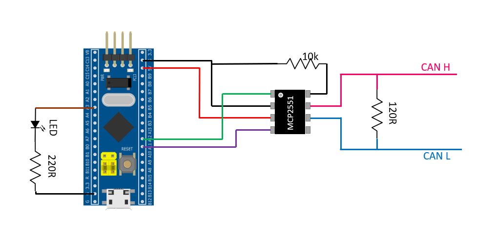
Make sure your CAN peripheral is configured in STM32CubeIDE (Normal Mode, correct baud rate, pins PA11 and PA12 enabled).
3.2. Writing the Task Code
Add the vCanTxTask function in the USER CODE BEGIN 4 section of main.c. This task will wait for data on the queue, and upon receiving it, will construct and send a CAN frame.
/* USER CODE BEGIN 4 */

void vCanTxTask(void *pvParameters)
{
    // CAN Header and Data variables
    CAN_TxHeaderTypeDef   TxHeader;
    uint8_t               TxData[8]; // CAN data payload can be up to 8 bytes
    uint32_t              TxMailbox; // Stores the mailbox used for transmission

    float temperature_to_send;

    // Configure the CAN Tx Header
    TxHeader.StdId = 0x100;         // Our chosen CAN ID for temperature data
    TxHeader.ExtId = 0;             // Not used
    TxHeader.RTR = CAN_RTR_DATA;    // We are sending a Data Frame
    TxHeader.IDE = CAN_ID_STD;      // We are using a Standard ID
    TxHeader.DLC = 4;               // Data Length is 4 bytes for a float
    TxHeader.TransmitGlobalTime = DISABLE;

    // Before starting the main loop, we must start the CAN peripheral
    if (HAL_CAN_Start(&hcan) != HAL_OK)
    {
        /* Start Error */
        Error_Handler();
    }

    for(;;)
    {
        // Wait until a message is received from the temperature queue
        if (xQueueReceive(temperatureQueue, &temperature_to_send, portMAX_DELAY) == pdPASS)
        {
            // A temperature value was successfully received. Now, package and send it.

            // Copy the 4 bytes of the float into our 8-byte TxData buffer.
            // Using memcpy is the safe and correct way to do this type-punning.
            memcpy(TxData, &temperature_to_send, sizeof(float));

            // Request transmission of the message
            if (HAL_CAN_AddTxMessage(&hcan, &TxHeader, TxData, &TxMailbox) != HAL_OK)
            {
                // Transmission request failed. Handle error here.
                // For now, we can just re-run the Error_Handler.
                Error_Handler();
            }
        }
    }
}
A quick note on memcpy: Directly casting a float pointer to a byte pointer and dereferencing it can violate C's strict aliasing rule, leading to undefined behavior with some compiler optimizations. memcpy is the standard, safe way to copy the byte representation of one type into a buffer of another type.
3.3. Launch the Task
Finally, create the CanTxTask in main() and make sure you've included <string.h> for memcpy.
/* Includes ------------------------------------------------------------------*/
/* USER CODE BEGIN Includes */


#include <string.h> // For memcpy
/* USER CODE END Includes */

// ... inside main() ...

/* USER CODE BEGIN 2 */
HAL_ADCEx_Calibration_Start(&hadc1);

adcSemaphore = xSemaphoreCreateBinary();
temperatureQueue = xQueueCreate(5, sizeof(float));

xTaskCreate(vTemperatureTask, "TempTask", 128, NULL, 1, NULL);

// Create the new CAN transmission task
xTaskCreate(vCanTxTask, "CanTxTask", 128, NULL, 1, NULL);
/* USER CODE END 2 */
4. Testing and Verification
Your system is now designed to read temperature, pass it to another task via a queue, and transmit it over CAN. But how do you verify it's working? Since you don't have a second CAN node yet to receive the message, your logic analyzer is the perfect tool for the job.
- Compile and Flash: Build the project and flash it to your Blue Pill board.
- Connect the Logic Analyzer: Connect a channel from your logic analyzer to the
CAN_TXpin (PA12) of your STM32. You can also connect to the CAN_H/CAN_L lines if your analyzer supports differential CAN decoding. - Configure Analyzer: Set up your logic analyzer software to use its CAN protocol analyzer. Configure it for the same baud rate you set in CubeMX.
- Capture and Analyze: Start a capture. You should see CAN frames appearing periodically (every 1 second, matching the
TemperatureTask's frequency).
Examine a captured frame. You should be able to verify:
- ID:
0x100 - DLC:
4 - Data: 4 bytes of payload. These bytes won't look like the temperature directly, as they are the raw
IEEE 754representation of the float value. The decoder might be able to interpret this for you if it's configured correctly.
STM32 CAN Communication Explained | Send & Receive Data Between Two Microcontrollers
The following video provides an excellent demonstration of using a logic analyzer to inspect CAN traffic. While the project is different, the process of capturing and decoding the frames is exactly what you need to do.
Watch from 14:39 to 16:30. Observe how the analyzer captures the CAN communication and breaks down a single frame, showing the ID, control field, and data bytes. This is precisely how you will verify that your CanTxTask is transmitting the correct information.
Conclusion
Excellent work. You have now implemented a complete sensor-to-bus data pipeline, a cornerstone of many embedded systems, particularly in automotive applications.
Key Takeaways:
- Queues for Inter-Task Communication: You used a FreeRTOS queue to safely and efficiently pass data from a producer task to a consumer task, effectively decoupling their logic.
- CAN Frame Construction: You learned how to programmatically define a CAN message by setting its Identifier (ID), Data Length Code (DLC), and payload (Data).
- HAL for CAN Transmission: You used
HAL_CAN_AddTxMessage()to hand off your constructed frame to the hardware for transmission. - Verification with a Logic Analyzer: You confirmed that the correct data is being sent on the physical bus, a critical debugging and verification skill.
Preview of the Next Lesson:
With data transmission working, our next step is to handle reception. In the next lesson, you will implement a CAN receive handler. This will involve configuring CAN acceptance filters to listen for specific message IDs and using an interrupt to process incoming messages, which we will use to control an actuator (like an LED) on your board. This will complete the communication loop for our automotive sensor node.