Introduction
Welcome to the final lesson of your course on becoming a professional Embedded Systems Engineer. Over the last eleven modules, you have journeyed from the fundamentals of microcontroller architecture to building a complex, real-time automotive sensor node. In our previous lesson, you made the capstone project bootloader-compatible, a crucial step for creating field-updatable products.
Your project is now technically complete. However, a brilliant project that no one can understand or appreciate has limited value in the job market. This final lesson is about bridging that gap. Today, you will learn how to transform your project from a folder on your local machine into a professional portfolio piece. This is the last step in showcasing your skills to recruiters and hiring managers, directly supporting your goal of becoming a job-ready firmware engineer.
This lesson will guide you through the final learning outcome: Structure the final project in a public Git repository, including a comprehensive README and a demonstration video. We will cover four key areas:
- Organizing your project's file structure for clarity and professionalism.
- Using Git and GitHub to publish your project, including a proper
.gitignorefile. - Writing a comprehensive
README.mdfile that acts as the front page for your project. - Planning a short, effective demonstration video to showcase your work.
1. Why a Professional Portfolio Matters
Before we dive into the "how," let's reinforce the "why." In a competitive field like embedded systems, a strong portfolio is what separates candidates. It provides concrete proof of your abilities beyond your CV.
Portfolio Projects That Get You Hired for Robotics Jobs
This article from RoboticsJobs.co.uk explains why a portfolio is so critical, especially in fields that blend hardware and software. It outlines what employers look for and how to present your work effectively.
Read the sections '1. Why a Robotics Portfolio Is Crucial', '2.3 Embedded Robotics Engineer', and '3. Anatomy of a Compelling Robotics Project'. These sections will frame the importance of our work today and give you a clear picture of what a hiring manager expects to see in an embedded project like yours.
As the article highlights, employers want to see that you can design, build, test, and document integrated systems. Your capstone project does all of that; now, we just need to present it professionally.
2. Structuring Your Project Directory
A clean, logical project structure makes your code easier to understand, maintain, and navigate. While STM32CubeIDE creates a default structure, we can improve upon it to reflect the layered architecture we discussed in Lesson 11.

The BEST Project Structure for C/C++/MCU | Embedded System Project Series #7
This video from Artful Bytes provides excellent insights into organizing files for an embedded C project. It moves beyond the defaults and discusses creating a structure that is both logical and practical.
Watch the video from 2:41 to 7:34. The presenter explains his chosen directory structure, which includes folders like src, external, docs, tools, and build. Pay close attention to how he sub-divides the src folder into app, drivers, and common. This is a model we can adapt for our capstone project.
Based on the principles from the video and our own project's architecture, here is a recommended structure. You don't have to follow it exactly, but it's a professional standard.
Action: In your project's root directory, create the following folders and move your existing files accordingly.
- /Src: Contains all your C source files (
.c).- Move
main.c,stm32f1xx_it.c, etc., here.
- Move
- /Inc: Contains all your header files (
.h).- Move
main.h,stm32f1xx_it.h, etc., here.
- Move
- /Drivers: This already exists. It should contain the STM32 HAL drivers and CMSIS files. No changes needed here.
- /Docs: A new folder for documentation.
- You can place block diagrams, photos of your hardware setup, or datasheets you referred to frequently.
- /Middlewares: This already exists and should contain the FreeRTOS source files. No changes needed here.
After reorganizing, you will need to update the include paths in STM32CubeIDE so the compiler can find your header files.
- Right-click your project -> Properties.
- Go to C/C++ Build -> Settings -> Tool Settings -> MCU GCC Compiler -> Include paths.
- Click the "Add" icon and add the
/Incfolder to the list. - Rebuild your project to ensure everything still compiles correctly.
This simple reorganization separates your application logic (Src, Inc) from vendor-provided files (Drivers, Middlewares) and documentation (Docs), making your project much cleaner.
3. Publishing to GitHub
With your project structured, it's time to put it under version control and share it on GitHub. We will use the EGit plugin integrated into STM32CubeIDE.
How to use Github with STM32cubeIDE in 2023
This guide from TavoTech provides a step-by-step walkthrough of connecting an STM32CubeIDE project to a GitHub repository. It covers everything from creating the repository to making your first commit.
Follow this guide carefully. It will walk you through: Creating a new public repository on GitHub. Generating a personal access token (this is used instead of your password). Installing the EGit plugin and cloning the repository into STM32CubeIDE. Crucially, creating a .gitignore file to exclude build files. The article provides a template you can copy and paste. Committing and pushing your project files.
A few key points to emphasize during this process:
- Create the repository on GitHub first. Make it public so that potential employers can see it. Do not initialize it with a README, license, or .gitignore; we will add these from our local project.
- The
.gitignorefile is essential. It prevents temporary build files, user-specific IDE settings, and debug artifacts from cluttering your repository. The template in the TavoTech article is a great starting point. - Write clear commit messages. A good first commit message would be "Initial commit of Automotive Sensor Node project." As you make changes, use descriptive messages like "Feat: Add FreeRTOS task for ADC reading" or "Fix: Corrected CAN bit timing for 500kbps."
Once you've pushed your project, you should see all your organized files on your GitHub repository page.
4. Crafting a Professional README.md
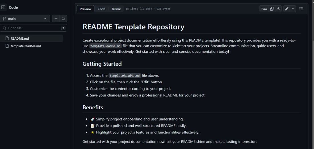
The README.md file is the most important part of your repository. It's the first thing anyone sees. A great README explains what the project is, why it's impressive, and how to use it.
How To Write a USEFUL README On Github
This video provides a fantastic breakdown of what makes a README useful and effective. It outlines an eight-part structure that serves as an excellent template for any portfolio project.
Watch from 3:59 to 8:26. The presenter details the essential components of a good README, from the title and introduction to diagrams, installation instructions, and more. Use these components as a checklist for your own README.
Action: In the root of your local project, create a file named README.md. Open it with a text editor (or directly in STM32CubeIDE) and use the following Markdown template. Fill it in with the specifics of your capstone project.
# Automotive Sensor Node with FreeRTOS and CAN Bus
A real-time embedded systems project that simulates an automotive sensor node using an STM32F103C8 microcontroller. The system reads an internal temperature sensor, packages the data, and transmits it over a CAN bus. It runs on the FreeRTOS operating system for concurrent task management.

*(Action: Take a clean, well-lit photo of your hardware setup and add it to the /Docs folder)*
---
## 🚀 Features
* **Real-Time Operating System:** Utilizes FreeRTOS for multi-tasking. Dedicated tasks for sensor acquisition and CAN communication.
* **Automotive Communication:** Implements the CAN protocol to transmit sensor data at 500kbps.
* **Data Acquisition:** Reads the STM32's internal temperature sensor using the ADC and DMA for efficient, non-blocking data transfers.
* **System Architecture:** Built on a layered firmware architecture (Application, Drivers, HAL) for modularity and maintainability.
* **Error Handling:** Includes a system-wide error handling mechanism that uses a dedicated FreeRTOS task to manage faults.
* **Bootloader Ready:** The application is configured to run from an offset memory address, making it compatible with a custom bootloader for firmware updates.
---
## 🛠️ Hardware & Software Stack
### Hardware
* **MCU:** STM32F103C8T6 ("Blue Pill")
* **CAN Transceiver:** TJA1050 / SN65HVD230
* **Debugger:** ST-Link V2
* **Display:** I2C LCD 1602 (Optional, for debugging)
* **Tools:** USB-to-CAN Analyzer, Logic Analyzer
### Software
* **IDE:** STM32CubeIDE
* **Frameworks:** STM32 HAL, FreeRTOS
* **Language:** C
---
## ⚙️ System Architecture
*(Optional but recommended: Create a simple block diagram showing the tasks, peripherals, and data flow (e.g., ADC/DMA -> Sensor Task -> Queue -> CAN Task -> CAN Bus). Add it to the /Docs folder and link it here.)*
---
## 🔧 Building and Running
1. Clone the repository.
2. Open the project in STM32CubeIDE.
3. Ensure the toolchain and dependencies are correctly configured.
4. Build the project using the "Build" button (hammer icon).
5. Flash the generated binary (`.elf` or `.bin`) to the target board using the ST-Link debugger.
6. Connect a CAN analyzer to the bus to view the transmitted messages (ID: `0x123`, 8-byte payload with temperature data).
---
## 🎥 Demonstration
*(Action: After creating your video, upload it to YouTube as an 'unlisted' video and paste the link here.)*
[Link to YouTube Demonstration]
Once you've written your README, commit and push it to your GitHub repository.
5. Creating an Effective Demonstration Video
A short video is the most powerful way to demonstrate a project that involves hardware. It brings your work to life.
As recommended in the RoboticsJobs article, a 2-3 minute video is ideal. Your video should include:
- Introduction (15-20 seconds):
- Briefly state your name and the project's purpose.
- Show a clear, wide shot of the entire hardware setup. Point out the key components (MCU, CAN transceiver, CAN analyzer).
- Demonstration (1-2 minutes):
- Show the system in action. A great way to do this is with a split-screen or by cutting between shots:
- Shot 1: The hardware, perhaps with an LED blinking to show it's alive.
- Shot 2: A screen recording of your CAN analyzer software, showing the messages being received from your board.
- Shot 3 (if applicable): The I2C LCD displaying the temperature.
- Narrate what is happening. For example: "Here you can see the STM32 board running the firmware. A FreeRTOS task is reading the internal temperature sensor once per second. This data is then passed to another task, which packages it into a CAN message with ID 0x123 and transmits it over the bus. On the screen, you can see the CAN analyzer receiving these messages in real time."
- Show the system in action. A great way to do this is with a split-screen or by cutting between shots:
- Conclusion (15 seconds):
- Briefly summarize the project's key technologies (FreeRTOS, CAN, DMA).
- Mention that the source code is available on your GitHub (you can even show the GitHub page on screen briefly).
You don't need a professional studio. A smartphone camera, good lighting, and a clear voice are all you need. Upload the video to YouTube as "unlisted" and add the link to your README and your LinkedIn profile.
Conclusion
Congratulations! You have officially completed the final lesson and, with it, the entire course. You have not only built a complex and relevant embedded project but have now packaged it into a professional portfolio piece ready to be shown to the world.
Key Takeaways from Today's Lesson:
- Professional Presentation is Key: A great project needs great documentation to be recognized.
- Structure Matters: A clean file structure communicates professionalism and makes your code understandable.
- The README is Your Elevator Pitch: It must clearly and concisely sell your project, highlighting its most impressive features and technologies.
- Show, Don't Just Tell: A short demonstration video provides undeniable proof of your hardware and software integration skills.
What's Next?
Your journey to becoming a professional embedded systems engineer is well underway. You now have a solid foundation in bare-metal and RTOS-based development, hands-on experience with key peripherals and automotive protocols, and a capstone project to prove it.
Your next steps are to:
- Build Your Portfolio: Add two more projects. Consider a project involving a different communication protocol (like SPI with an external flash chip), a low-power application, or one that requires writing a basic bootloader.
- Refine Your CV and LinkedIn: Add this capstone project to your experience, with a direct link to your new GitHub repository.
- Start Applying: You now have the practical skills and the portfolio to confidently apply for junior firmware and embedded systems engineering roles.
Thank you for your dedication throughout this course. The skills you have built are in high demand, and I am confident in your ability to succeed in this exciting field. Good luck