Hello! Let's dive into the next step of building our system models.
In the past two lessons, we've established how many state variables we need (the system's order) and which physical quantities to choose for them (based on energy storage). Today, we'll put it all together. Our goal is to derive state-space models from differential equations for linear time-invariant (LTI) systems. This means we'll learn the systematic procedure for converting the equations that describe a system's physics into the powerful matrix format used for modern control design.
This is the process that takes us to the standard state-space representation:
Let's look at a block diagram to visualize what we're building.
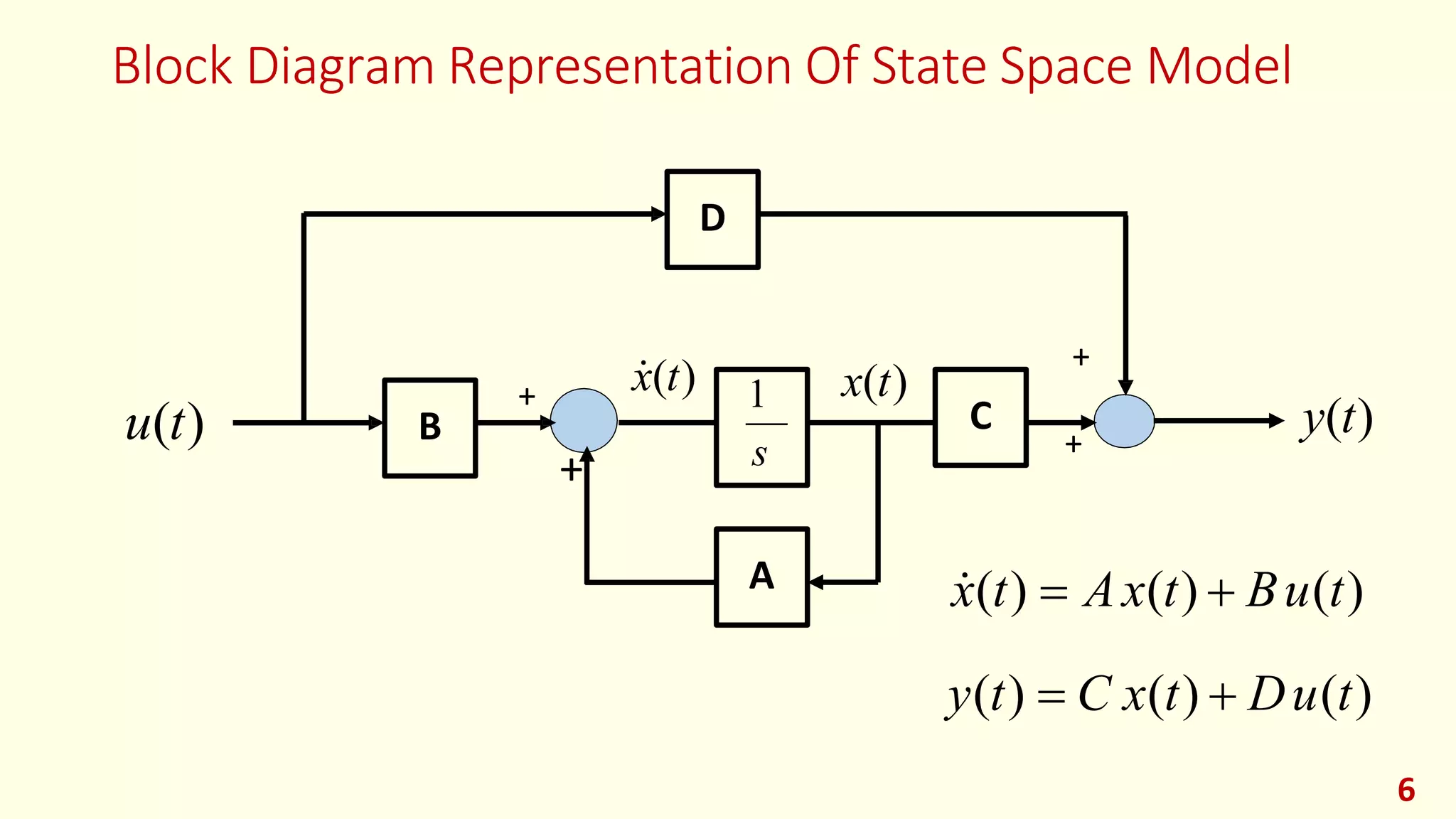
From Nth-Order DE to a System of First-Order Equations
The core idea of a state-space model is to represent a system using only first-order differential equations. So, if we start with a single -th order differential equation, our first task is to break it down into first-order equations.
The most straightforward way to do this involves defining a chain of state variables, where each new variable is the derivative of the last.
For an -th order differential equation involving a variable , we can define the state variables as:
- (the variable itself)
- (its first derivative)
- (its second derivative)
- ...
- (its -th derivative)
This clever choice gives us state equations almost for free:
- ...
The final equation, for , comes from rearranging the original differential equation to solve for its highest derivative.
The following video provides an excellent demonstration of this exact process.
System Dynamics and Control: Module 27a - Introduction to State-Space Modeling
Let's watch 'System Dynamics and Control: Module 27a - Introduction to State-Space Modeling' from the Rick Hill channel. This video clearly illustrates how to take a third-order differential equation and convert it into the A, B, C, and D matrices.
Please watch from 01:58 to 05:00 to see the state variables being defined and the state equations derived. Then, watch from 07:48 to 11:41 to see how these equations are assembled into the final matrix form. The segment from 05:00 to 06:00 on the output equation is also important.
The Resulting Structure: Controllable Canonical Form
When you use this specific method of choosing state variables (, etc.) for a differential equation with no derivatives of the input, the resulting and matrices have a very specific and useful structure.
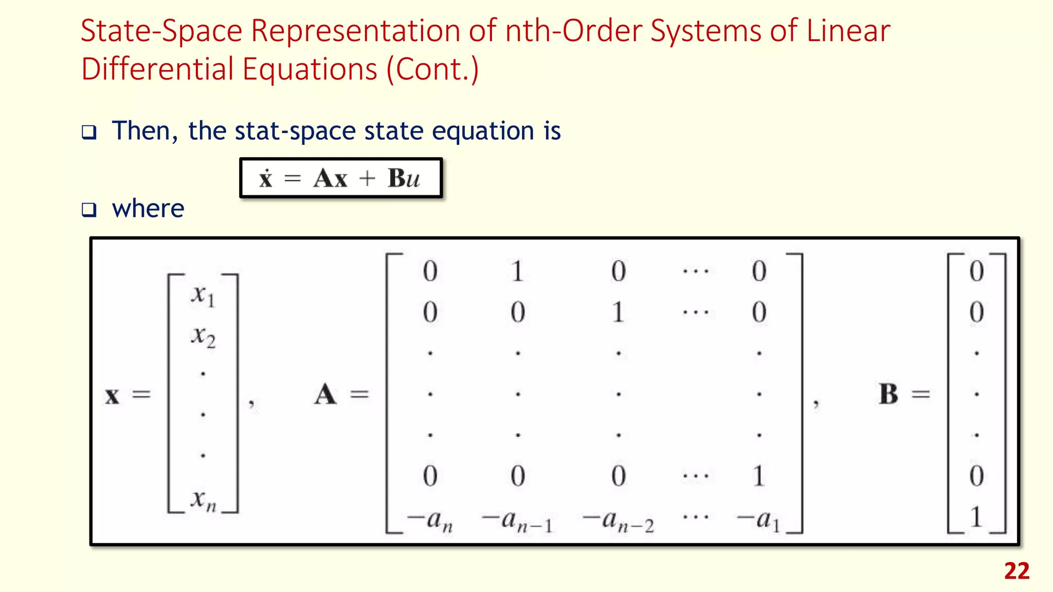
This structure is called Controllable Canonical Form. Recognizing this pattern can be a significant shortcut. Once you've rearranged your differential equation in the standard form (highest derivative on the left), you can often write down the and matrices directly by inspection.
Test your understanding!
Given the following second-order differential equation for a system with input and output :
Derive the state-space model in the form and . Use the state variable definition and .
Show answer
-
Define State Variables:
-
Derive State Equations:
- . In terms of state variables, this is .
- . From the original DE, we rearrange to solve for :
Substituting the state variables:
-
Define Output Equation:
The output is , which we defined as . -
Assemble Matrices:
From the state and output equations, we assemble the matrices:Notice how the matrix follows the Controllable Canonical Form structure, with the coefficients and appearing in the last row.
From Physical Laws to State-Space Models
More often, instead of starting with a single high-order differential equation, you will start with a physical system. As we saw in the last lesson, you can use physical principles to choose your state variables (inductor currents, capacitor voltages, etc.). You then apply physical laws (Kirchhoff's, Newton's) to write a set of coupled equations and rearrange them into state-space form.
Since your background is in Electrical Engineering, let's focus on an RLC circuit. This approach should feel very natural.
The General Process:
- Choose State Variables: As per our previous lesson, pick inductor currents and capacitor voltages.
- Write Dynamic Equations: Apply Kirchhoff's Voltage Law (KVL) for loops containing inductors and Kirchhoff's Current Law (KCL) for nodes connected to capacitors.
- Isolate Derivatives: Manipulate these equations algebraically to get an expression for each state variable's derivative ( or ) on the left-hand side.
- Substitute: Ensure the right-hand side of each equation contains only state variables and inputs, no other derivatives.
- Assemble Matrices: Collect the coefficients into the matrices.
The following document walks through several excellent examples for both electrical and mechanical systems.
Let's study the document 'ECEN 605 - Linear Systems' from Texas A&M University. It provides clear, university-level examples of deriving state-space models directly from physical laws.
Please read the section 'Examples of State Space Models' (starting on page 8). Focus on the first RLC circuit example (pages 9-11) and the first mechanical system example (pages 31-34). Observe how KVL/KCL and Newton's laws are used to build the equations that are then formed into the A and B matrices.
This method of deriving equations from physical laws is generally more powerful than converting a single high-order DE, especially for Multi-Input Multi-Output (MIMO) systems where interactions can be complex.
An Even Deeper Dive (Optional)
The process of converting from a differential equation can become more complex if the input side also includes derivatives (which corresponds to having zeros in a transfer function). The general method remains the same, but the resulting and matrices (or matrix, depending on the chosen canonical form) will be different.
The video below explains this process in great detail, including the shortcut for reading coefficients and the reasoning behind it, and also handles the case with input derivatives.
From Differential Equation to State Space Equations [2 Examples]
For a more comprehensive look, 'From Differential Equation to State Space Equations [2 Examples]' by digitidea provides a rapid method and explains the underlying derivation.
Watch the first part (05:17 to 08:11) to see a 'shortcut' for writing the matrices. Then, watch the detailed explanation (08:11 to 19:53) to understand why it works. If you're curious, the final part (19:53 to 24:38) shows how to handle derivatives of the input, which is a common scenario in signal processing and control.
Conclusion
In this lesson, you've learned the essential skill of translating a system's dynamic equations into the standard state-space matrix representation.
Key Takeaways:
- A state-space model represents an -th order system as a set of coupled first-order differential equations.
- Path 1: From a single DE: You can define state variables as successive derivatives of the output (). This often leads to the Controllable Canonical Form.
- Path 2: From physical laws: You can choose physically meaningful state variables (based on energy storage) and use first principles (like KVL/KCL or Newton's laws) to derive the coupled first-order equations directly. This is the more general and powerful method for complex systems.
- In all cases, the final step is to algebraically arrange the equations to isolate the state derivatives () and assemble the coefficients into the and matrices.
Preview of the Next Lesson:
The methods we've learned today are for Linear Time-Invariant (LTI) systems. However, many interesting systems, including your rotary inverted pendulum project, are fundamentally nonlinear. In our next lesson, we will tackle this by learning how to linearize a nonlinear system model around an operating point. This will allow us to create an approximate LTI state-space model that is valid near a specific equilibrium, making it suitable for the linear control techniques we will study later.