Hello! Welcome to the next step in creating your project documentation.
In the last lesson, you created detailed, dimensioned drawings for the individual wooden parts of your desk. You now have the plans to fabricate each piece. Today, we'll focus on how to assemble them.
This lesson addresses the learning outcome: Create an exploded view of the assembly to illustrate the construction sequence. An exploded view is a standard feature in technical documentation, showing components separated but in their proper orientation for assembly. For your desk project, this will serve as the master guide for how everything fits together. We will accomplish this using Fusion 360's Animation workspace.
1. Welcome to the Animation Workspace
While the name might suggest complex character animation, the Animation workspace in Fusion 360 is primarily a powerful tool for creating technical animations, such as assembly/disassembly sequences, and for generating static exploded views for drawings.
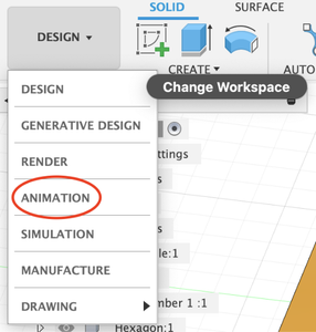
To get started, you'll switch from the "Design" or "Drawing" workspace to "Animation".
Once you enter the workspace, you'll see a new interface at the bottom of the screen. The key elements are:
- Storyboard: This contains a single, complete animation sequence. You can have multiple storyboards (e.g., one for disassembly, one for assembly).
- Animation Timeline: This is where all your component movements and camera changes are recorded as "actions".
- Playhead: The vertical marker that you can drag to scrub through the timeline and set the timing for new actions.
A critical point to remember, which we've reinforced throughout the course, is that the Animation workspace operates on components. Bodies that have not been converted to components cannot be animated individually.
2. Creating an Exploded View: The Manual Approach
The most professional and controlled way to create an exploded view is by manually transforming each component. The general strategy is to create a disassembly sequence first, as it's often more intuitive to pull a model apart.
The core tool for this is Transform Components (shortcut M), which allows you to move and rotate selected components. Each transformation, when the playhead is on the timeline, is recorded as an action.
Autodesk Fusion | Module 9: Creating an animation for assembly instructions
Let's watch a detailed walkthrough from Autodesk Education on how to create a disassembly sequence step-by-step. This video clearly explains how to sequence the movement of parts and adjust their timing on the timeline.
Watch the segment from 01:44 to 06:52. Pay close attention to these key steps: Setting the Playhead: Notice how the playhead is moved forward in time before a component is moved. The duration from the previous action to the playhead's new position becomes the duration of the new movement. Using Transform Components: Observe the process of selecting a component (like the bolts or the pin) and dragging it to a new position. Trail Visibility: The Trail Visibility option is enabled to create the lines that show the path of each component, which is characteristic of an exploded view. Adjusting the Timeline: See how the action bars in the timeline can be dragged to change when a movement starts and how long it takes. This allows you to stagger the movements so parts explode sequentially rather than all at once.
This manual control is essential for creating a logical sequence that reflects the actual order of assembly. For your desk, you might first move the screws, then the leg brackets, then the legs themselves.
A Quick Alternative: Auto Explode
Fusion 360 also offers an Auto Explode tool. It's very fast but offers little control over the direction and order of the explosion. It can be a good starting point, but manual adjustments are almost always necessary for a clear and logical result.
Getting Started Creating ANIMATIONS in Fusion 360 - Beginners Start Here!
To see how this quick method works, watch this short clip from Product Design Online.
Watch from 01:50 to 03:11. This demonstrates how Auto Explode works and highlights a key takeaway: its limitations often require you to use manual methods for a polished result.
3. From Disassembly to Assembly with One Click
Once you have a complete disassembly animation, you don't need to do all that work again to show the assembly. You can simply create a reversed copy of your disassembly storyboard.
Autodesk Fusion | Module 9: Creating an animation for assembly instructions
The Autodesk Education video demonstrates this efficient workflow.
Watch from 06:52 to 08:29. The process is simple but powerful: Copy the existing storyboard. Paste it as a new storyboard. (Recommended) Rename the storyboards to 'Disassembly' and 'Assembly' for clarity. Right-click the 'Assembly' storyboard and select Reverse.
This simple trick saves a significant amount of time and ensures your assembly sequence is a perfect mirror of your disassembly sequence.
4. Publishing Your Work
An exploded view is a communication tool, so you need to export it in a usable format. There are two primary outputs from the Animation workspace.
Output 1: Animated Video (MP4)
This creates a video file of your animation, which is perfect for digital assembly guides.
Getting Started Creating ANIMATIONS in Fusion 360 - Beginners Start Here!
Publishing a video is straightforward. This clip from Product Design Online shows the final step.
Watch from 08:35 to 09:13. The key command is Publish Video, where you can choose which storyboard to export and set the video resolution.
Output 2: Static Drawing View
This is arguably the more critical output for your capstone documentation. You can use your animation to create a static, pictorial view for a printed assembly manual. You can generate a drawing directly from the Animation workspace, choosing a storyboard and a specific point in time to capture as the view.

Autodesk Fusion | Module 9: Creating an animation for assembly instructions
Let's return one last time to the Autodesk Education video, which covers this process perfectly.
Watch from 08:29 to 09:37. This segment shows how to use the Drawing from Animation command. Note how you can select the storyboard you want to use (e.g., your 'Disassembly' storyboard) and place it as a shaded, isometric view in a drawing. This directly connects today's lesson with what you learned previously about the Drawing workspace.
This ability to create a static exploded view is the foundation for our next lesson, where we will add part callouts and a parts list to create a complete assembly drawing.
Conclusion
You now have the skills to visually document the construction sequence of your designs. By creating a clear, step-by-step exploded animation, you not only help yourself plan the build but also create a professional guide for anyone else who might build your design.
Key Takeaways:
- The Animation workspace is used to create technical animations and exploded views.
- The most controlled method is to manually Transform Components and sequence the movements on the timeline.
- A highly efficient workflow is to animate the disassembly, then copy and reverse the storyboard to create the assembly animation.
- You can publish your work as an MP4 video for dynamic instructions or create a Drawing from Animation to generate a static exploded view for printed plans.
Next Lesson Preview:
In our final lesson of this module, we will build upon the static exploded view you just learned to create. We will add part number balloons (callouts) and a parts list to produce a complete, professional assembly drawing for your desk project.