Hello! Welcome to the final lesson in our module on Advanced Modeling & Design Refinement.
In our last lesson, we explored how to build complex parts using the Split Body and Combine tools. These are powerful commands for creating multi-part assemblies. However, the power of parametric modeling comes with a catch: when you have a long, interdependent history of features, a small change early on can sometimes cause a cascade of issues later in your design.
Today's Goal: Your learning outcome is to diagnose and resolve timeline errors like broken sketch references and failed features.
Mastering this skill is what separates a novice from an expert user. It gives you the confidence to edit and iterate on your designs—even complex ones for your future PC desk project—without the fear of "breaking" everything. Instead of starting over, you'll learn how to perform surgical repairs to keep your model healthy and robust.
1. Errors vs. Warnings: Understanding the Signals
When Fusion 360 encounters a problem in your timeline, it will notify you with either a yellow warning or a red error. Understanding the difference is the first step in diagnosing the problem.
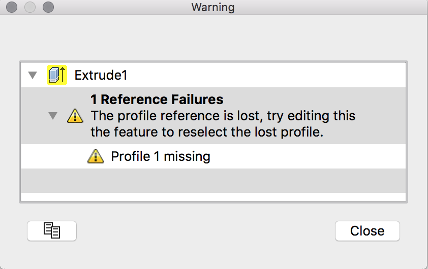
- Warnings (Yellow): A warning means a feature has lost a reference, but Fusion 360 is still able to compute a result using cached or old information. Your model might look correct, but it's no longer parametrically stable. This is a ticking time bomb; future changes are likely to fail.
- Errors (Red): An error is a catastrophic failure. The feature cannot be computed at all. This creates a "roadblock" in your timeline, and any subsequent features that depend on the failed one will also fail.

Let's watch a short video that quickly summarizes this distinction.
Smart strategies to fix model errors & warnings in your Design! | Autodesk Fusion 360
The video 'Smart strategies to fix model errors & warnings' from the official Autodesk Fusion channel provides a concise overview of the difference between errors and warnings.
Watch the segment from 0:23 to 0:51 to see the visual difference and understand the severity of each type.
2. The Core Issue: Broken Dependencies
Nearly all timeline errors are dependency errors. As you know from your engineering background, a parametric model is a sequence of dependent operations. An Extrude feature depends on a Sketch profile. A Fillet depends on a body's Edge. If the parent geometry is deleted or changed so drastically that Fusion can't find it anymore, the child feature's dependency is broken, and an error occurs.
For a deeper dive into the "why," the following document, written by a Fusion 360 developer, is an excellent resource. You don't need to memorize it, but understanding the core concepts will make you a much more effective troubleshooter.
[PDF] Debugging your Fusion Design: Let's get rid of those red and yellow ...
This handout from an Autodesk University class, 'Debugging your Fusion Design,' explains the underlying mechanics of timeline errors.
Please read pages 7 to 13. These sections cover: A Brief Introduction to Parametric Feature Design: Explains what dependencies are and their implications. The Difference Between Geometry and Topology Dependencies: This explains why some failures result in a yellow Warning (using cached geometry) while others cause a red Error (no way to recover). Focus on understanding the concepts of dependencies and why topology failures (like a missing edge for a fillet) are more severe than geometry failures (like a missing plane for a sketch).
A very common way dependencies are broken is by using the Delete command on components or bodies that other features reference.
Watch this segment to see what happens when you Delete a referenced part and why the Remove command is often a safer alternative for components.
Dealing with Timeline errors & warnings in Fusion
The video 'Dealing with Timeline errors & warnings in Fusion' by Brad Tallis clearly demonstrates a common cause of errors.
Watch from 1:52 to 5:08. This section shows how deleting a component creates a timeline error and introduces the Remove command as a safer way to get rid of components without breaking downstream references.
3. The Debugging Workflow: Strategies and Tools
When you see a sea of red and yellow in your timeline, don't panic. The strategy is simple and universal across all CAD software:
Rule #1: Roll the timeline marker back and fix the first error.
Often, a single root cause creates a domino effect. Fixing that first problem will frequently resolve many of the subsequent errors automatically.
Now, let's look at the specific tools for fixing the most common types of errors.
Scenario 1: The Sketch Plane is Lost
- Symptom: Your sketch has a yellow warning and says its plane is lost.
- Cause: The face or plane you originally created the sketch on has been deleted or fundamentally changed.
- Solution: Right-click the sketch in the timeline and select
Redefine Sketch Plane. Then, simply select a new, valid plane or face.
Scenario 2: Projected Geometry Reference is Lost
- Symptom: A sketch has a warning, and inside the sketch, projected lines are yellow or brown instead of purple.
- Cause: The original edge or vertex you projected has been removed or altered.
- Solution: Right-click the sketch in the timeline and select
Manage Lost Projections. This dialog lets you:- Re-Link: Select a new piece of geometry to replace the lost one.
- Break Link: Convert the projected line to a regular, fixed sketch line, severing the parametric link.
- Delete: Remove the dead projection.
Scenario 3: A Feature Fails (Extrude, Fillet, Combine, etc.)
- Symptom: A modeling feature like
ExtrudeorFilletturns red or yellow. The error message often says a profile, tool body, or edge is missing. - Cause: The geometry the feature was targeting (e.g., the sketch profile for an extrude, the edge for a fillet) is no longer available.
- Solution: Right-click the feature in the timeline and select
Edit Feature. The dialog box will usually highlight the missing reference in red. Clear the old selection and re-select the correct, new geometry.
This next video demonstrates how to apply these exact solutions to a model with multiple errors.
Dealing with Timeline errors & warnings in Fusion
Let's return to Brad Tallis's video. He does an excellent job walking through the repair process for several different error types.
Please watch the following segments demonstrating these fixes: Fixing Projections and Sketch Planes (5:08 - 7:10): A clear demonstration of Manage Lost Projections and Redefine Sketch Plane. Identifying Error Types (7:10 - 9:55): Shows how to interpret warning messages for a complex model with both yellow warnings (lost projections) and red errors (failed Combine feature). Fixing an Extrude Feature (10:31 - 12:21): After fixing a sketch, the extrude that uses it also shows a warning. This demonstrates re-selecting the profiles in the Edit Feature dialog. Fixing a Joint Feature (13:43 - 15:20): Shows the same Edit Feature principle applied to an assembly joint that has lost one of its references.
4. Your Turn: Practice Breaking and Fixing
The best way to learn debugging is to do it. Let's intentionally create and then fix a common error.
Task: Fix a Broken Sketch Reference (10 minutes)
-
Create a Base Model:
- Create a new design.
- Sketch a
Center Rectangle(60mm x 40mm) on the ground plane andExtrudeit up by 30mm. - Use the
Fillettool to round all 4 vertical edges with a radius of 5mm.
-
Create a Dependent Feature:
- Use
Construct > Offset Planeto create a new plane offset from one of the large, flat faces of the body by 15mm. - Create a new sketch on this offset plane.
- In the sketch, draw a circle anywhere. Finish the sketch.
- Use
-
Break the Dependency:
- Find the
Filletfeature in your timeline. Right-click andEdit Feature. - Change the fillet radius to 25mm. This is large enough that the original flat face you referenced for your offset plane will completely disappear.
- Click OK. Observe the timeline. You should see yellow warnings on your
Offset Planeand yourSketch.
- Find the
-
Fix the Error:
- Right-click on the
Sketchfeature with the warning. - Select
Redefine Sketch Plane. - Your model will become temporarily transparent, and Fusion will prompt you to select a new plane.
- Select one of the Origin Planes (e.g., the YZ or XZ plane) from the browser tree on the left.
- Click OK.
- Right-click on the
The errors on both the plane and the sketch should now be resolved. You've successfully repaired the model by re-anchoring the dependent features to a stable reference (an origin plane).
Conclusion
You've now learned the essential skills for maintaining the health of your parametric designs. This isn't just about fixing things when they break; it's about building with the confidence that you can fix them, which unlocks the true potential for rapid iteration and complex design.
Key Takeaways:
- Errors (Red) are catastrophic failures, while Warnings (Yellow) indicate an unstable feature using outdated information.
- Most errors are caused by broken dependencies—a child feature losing its parent reference geometry.
- Always debug by starting with the first error in the timeline.
- Your primary repair tools are
Redefine Sketch Plane,Manage Lost Projections, andEdit Featureto re-select missing references. - For maximum stability, reference robust geometry like Origin Planes whenever your design intent allows.
Next Lesson Preview:
In this lesson, we worked on a relatively simple model. On a complex project like your PC desk, the timeline can have hundreds of features. Finding the exact feature you want to edit can be a challenge in itself. In our next and final lesson of this module, we will cover how to use the 'Find in Timeline' feature to locate a specific feature from the 3D model, an essential navigation skill for large projects.