Hello! Welcome to the next lesson in your journey to mastering Fusion 360.
In our last session, we focused on applying geometric constraints to define the shape and relationships within a sketch. You learned that this "constraints-first" approach is the professional way to embed your design intent, creating sketches that behave predictably. However, these sketches were still blue, meaning their size and position were not yet fixed.
Today, we will complete the process by adding dimensions to create a fully constrained sketch. You will learn how to use the dimensioning tool to lock down the size and location of your geometry, turning it from flexible blue lines into robust, unchangeable black lines. This is the final and crucial step in creating a stable foundation for your 3D models.
1. Why We Aim for Fully Constrained Sketches
Before we dive into the "how," let's solidify the "why." A fully constrained sketch has no ambiguity. Every point, line, and curve is precisely where you intended it to be, and it won't move by accident. This stability is paramount when you start building complex, multi-part designs for your gaming accessories or desk project.
The video below provides a great overview of what "fully constrained" means and demonstrates the pitfalls of modifying a design that isn't locked down.
HOW and WHY to Fully Constrain Your Sketches - Learn Autodesk Fusion 360 in 30 Days: Day #17
Let's watch two key segments from the video "HOW and WHY to Fully Constrain Your Sketches" by Product Design Online. The first part introduces the concept, and the second powerfully illustrates the problems with an unconstrained sketch.
First, watch the introduction from 00:00 to 01:14 to understand the concept of design intent and full constraint. Then, jump to the end and watch from 13:21 to 14:25 to see a direct comparison between a constrained and an unconstrained model being edited.
As you saw, an unconstrained sketch can fall apart when you try to make simple changes. A fully constrained sketch, indicated by all geometry turning black, prevents this.

2. The Sketch Dimension Tool
The primary tool for this task is the Sketch Dimension tool. You can activate it by pressing the D key on your keyboard—this is one of the most common shortcuts you'll use.
With this single tool, you can define lengths, distances, diameters, radii, and angles. Fusion 360 is context-aware; the dimension type it creates depends on what you click.
- Click a line: Creates a length dimension.
- Click two parallel lines: Creates a distance dimension between them.
- Click a circle: Creates a diameter dimension.
- Click an arc: Creates a radius dimension.
- Click two non-parallel lines: Creates an angle dimension.
The following video provides a clear, practical guide to applying these different dimension types.
Fusion 360 - Sketch Dimensions Beginner's Guide
Let's watch segments from Tyler Beck's "Fusion 360 - Sketch Dimensions Beginner's Guide." This will show you how to apply the most common dimension types.
Please watch the following three clips: Linear Dimensions (01:09 - 02:18): See how to dimension a rectangle. Angular and Aligned Dimensions (02:18 - 04:14): Learn the difference between horizontal/vertical distance and the true length of a line (aligned dimension), and how to add angles. Circle and Arc Dimensions (07:40 - 10:00): Observe how to dimension circles (diameter vs. radius) and arcs.
3. Workflow: Constraints First, Dimensions Second
Now, let's put everything from the last two lessons together. The most efficient workflow is to first define the sketch's shape and logic with constraints, then use a minimal number of dimensions to define its size and position.
We'll watch a step-by-step example of creating a square washer. Pay close attention to how constraints (like Equal and Coincident) are applied first, which drastically reduces the number of dimensions needed to fully define the sketch.
HOW and WHY to Fully Constrain Your Sketches - Learn Autodesk Fusion 360 in 30 Days: Day #17
Let's return to the "HOW and WHY to Fully Constrain Your Sketches" video. This section demonstrates the ideal workflow from start to finish.
Watch from 01:14 to 09:55. Notice how using a Center Rectangle and Equal constraint means only ONE dimension is needed to define the entire square. Also, see how constraining the sketch to the origin locks its position.
This workflow is the core of effective parametric modeling. By making the sides equal first, a single 100mm dimension defines the entire square. Without that constraint, you would have needed at least two dimensions and a perpendicular constraint, or even more.
4. Driving vs. Driven Dimensions (Avoiding Errors)
What happens if you try to add a dimension that conflicts with an existing one, or one that is redundant? Fusion 360 will give you an "over-constrained" warning.
When this happens, you have two choices:
- Cancel the new dimension.
- Accept it as a Driven Dimension.
A driving dimension (the default) controls the sketch. If you change its value, the sketch geometry updates. A driven dimension is just a reference measurement; it's shown in parentheses and cannot be edited. It will update if other driving dimensions change it.
How to Dimension Sketches in Fusion 360
The article "How to Dimension Sketches in Fusion 360" has a great, concise explanation of this concept. Reading this will help you understand the feedback Fusion 360 gives you.
In the article, find the section titled '7 Tips that Will Make You a Dimension Expert' and read Tip #3, 'Driving vs Driven Dimensions'.
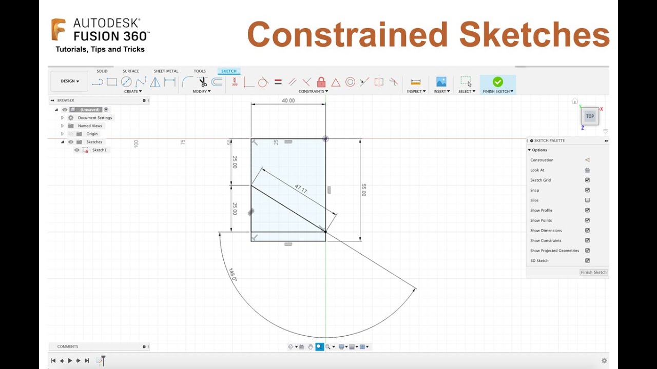
5. A Glimpse of Parametric Power
Dimensions don't have to be static numbers. They can contain formulas or refer to other dimensions. This is a foundational concept of parametric design, which we will cover in-depth in a future module. For now, let's see a simple, powerful example.
Imagine you want the hole in the washer to always be half the size of the outer square. Instead of manually calculating it, you can tell Fusion 360 to do it for you.
HOW and WHY to Fully Constrain Your Sketches - Learn Autodesk Fusion 360 in 30 Days: Day #17
Let's watch one more clip from the Product Design Online video. This section introduces using simple equations inside a dimension.
Watch from 09:55 to 13:21. Pay attention to how the dimension of the circle is defined by referring to the square's dimension (d1). When d1 changes, the circle automatically updates.
This is an incredibly powerful technique for creating flexible designs that can be easily resized.
6. Practice: Fully Constraining the Link
It's time to apply what you've learned. In the previous lesson, you created a symmetrical link sketch that was constrained for shape. Now, you will add dimensions to constrain its size and position.
- Open the symmetrical link sketch you created in the last lesson. The geometry should be blue.
- Press the
Dkey to activate the Sketch Dimension tool. - Dimension the size:
- Click on one of the circles and place its diameter dimension. Enter a value, for example,
10mm. Because you used anEqualconstraint, the other circle will update automatically. - Click on the center point of each circle. Place the dimension for the distance between them. Enter a value, for example,
40mm.
- Click on one of the circles and place its diameter dimension. Enter a value, for example,
- Dimension the position:
- Your sketch can still be dragged around the screen. To fix its position, we need to lock it to the origin.
- Activate the Coincident constraint.
- Click on the midpoint of your vertical construction line, then click on the sketch origin point. The entire sketch should snap into place.
- Check your work: All the lines of your sketch should now be black. You have a fully constrained sketch! Try to drag any part of it; you won't be able to.
Conclusion
Congratulations! You have now mastered the two fundamental components of a robust sketch: geometric constraints and dimensions. By combining these, you can create sketches that are precise, stable, and intelligent.
Key Takeaways:
- A fully constrained sketch has all its geometry colored black, meaning it cannot be accidentally moved or resized.
- The standard workflow is to define the shape with constraints first, then define the size and position with a minimal number of dimensions.
- The Sketch Dimension tool (
Dkey) is used to define lengths, distances, angles, diameters, and radii. - A driving dimension controls the sketch, while a driven dimension (in parentheses) is a read-only measurement used for reference.
- You can use formulas and references to other dimensions to create powerful parametric relationships.
In our next lesson, we will take a step back to discuss the broader importance of fully constraining sketches for creating stable and predictable models, reinforcing why the skills you've just learned are so critical as your designs become more complex.