Hello! Welcome back.
In our last lesson, we explored the Press Pull tool, a versatile command for modifying existing geometry. We saw that you could use it to change the diameter of a hole, but I also mentioned there's a more powerful and specialized tool for creating holes from scratch. Today, we're going to master that tool.
This lesson focuses on the Hole tool. For someone with a mechanical engineering background, you'll appreciate that this tool isn't just about cutting a cylinder through a part; it's about embedding design intent. It allows you to create standardized holes for specific fasteners—a critical step for assembling the 3D printed parts and DIY projects you plan to build.
By the end of this lesson, you will be able to create various hole types (simple, counterbore, and countersink) using the Hole tool.
1. Beyond the Simple Cut: Why Use the Hole Tool?
You could create a hole by sketching a circle and using the Extrude tool to cut it. For a simple opening, that works perfectly fine. However, when you're designing parts that need to be assembled with screws and bolts, this method becomes tedious and error-prone. You'd have to sketch and extrude multiple concentric circles or use a revolved cut to create the shapes needed for screw heads.
The Hole tool automates this process. It's a dedicated feature that packages all the necessary geometry for standard fastener types into a single, intelligent command.
Let's start with a quick introduction to the Hole command and its advantages.
Fusion 360 Hole Command – The Fastest Way to Add Holes, Threads & Countersinks
This video from Tyler Beck of Tech & Espresso introduces the Hole command and immediately shows how much faster it is for creating a countersink compared to manual sketching.
Watch from the beginning to 02:42. Pay attention to how the Hole tool's dialog box provides options to create a complex shape like a countersink in a single step.
As the video demonstrates, the Hole tool is not just faster; it creates a more robust and editable feature in your timeline.
2. The Anatomy of a Hole: Simple, Counterbore, and Countersink
The Hole tool can create many types of holes, but for assembly purposes, we will focus on the three most common ones.
-
Simple Hole: A straight, cylindrical hole. Used for clearance (where a bolt passes through freely) or for tapping threads directly into the material.
-
Counterbore Hole: A simple hole with a larger cylindrical cutout at the top. This allows the head of a fastener, like a Socket Head Cap Screw or a hex bolt, to sit flush with or recessed below the surface. This is common in machine design and 3D prints to hide screw heads.

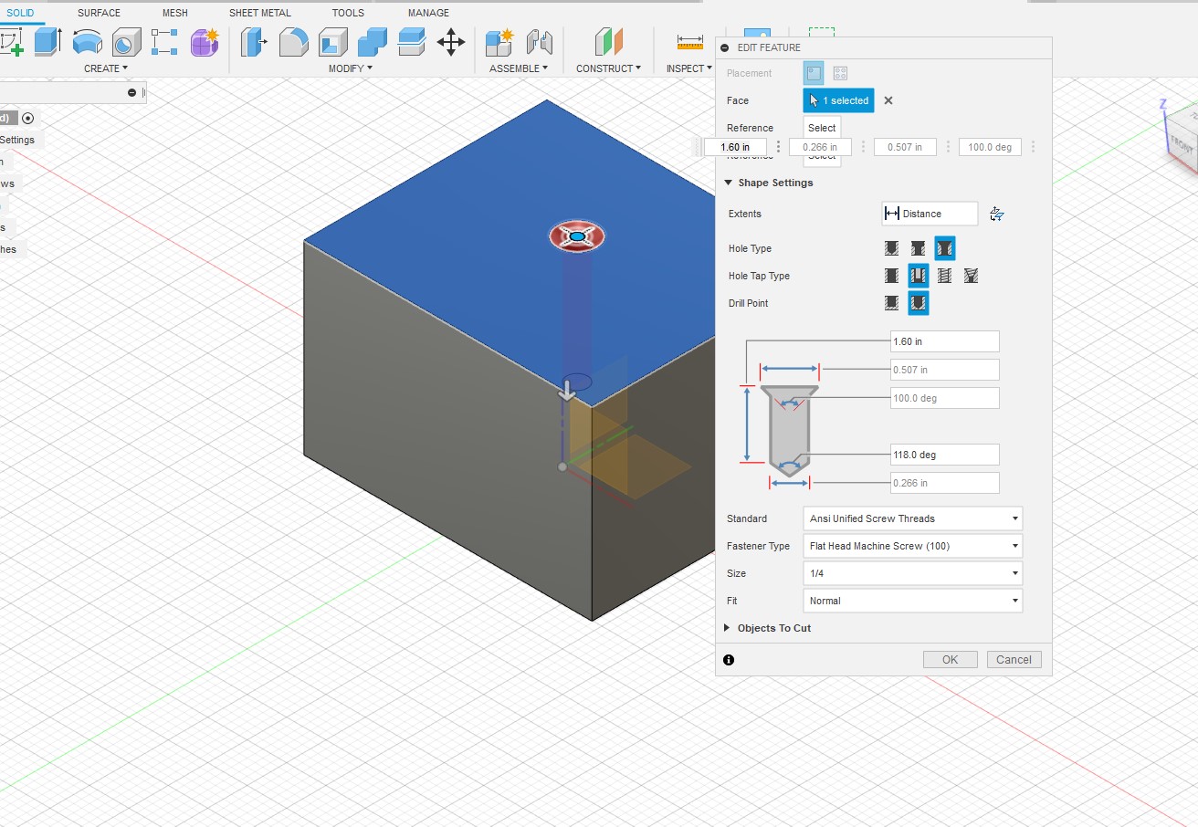
- Countersink Hole: A simple hole with a conical cutout at the top. This is designed for flat-head screws, allowing the screw head to sit perfectly flush with the surface for a smooth finish. This is very common in woodworking and consumer products.
3. Creating Standardized Holes
The real power of the Hole tool lies in its built-in library of fastener standards. Instead of manually looking up the head diameter and depth for an "M5 Socket Head Cap Screw," you can simply select it from a dropdown menu.
Let's see how this works for a counterbore, which is one of the most useful hole types for your projects.
Fusion 360 Hole Command – The Fastest Way to Add Holes, Threads & Countersinks
Continuing with the video from Tyler Beck, this section demonstrates creating a counterbore hole that cuts through two separate components—a common scenario in assemblies.
Watch from 09:18 to 12:23. Focus on how he uses the dialog to select the hole type (Counterbore), fastener type (Socket Head), size (M10), and fit (Close, Loose). These options add a high level of precision to your design.
The ability to specify the Fit (Close, Normal, Loose) is particularly useful for 3D printing. You can start with a Normal fit and, if you find your printer's tolerances make the hole too tight, you can easily edit the feature and change it to Loose to add more clearance.
4. Placing Multiple Holes Efficiently
For a single hole, you can place it by dragging it or by using the Reference option in the dialog to dimension it from edges. But what if you need a pattern of four holes for a mounting plate? Creating them one by one would be inefficient.
The best method is to use sketch points. You create a sketch, place points where you want the centers of your holes to be, and then use the Hole tool to target all those points at once.
Fusion 360 Hole Command – The Fastest Way to Add Holes, Threads & Countersinks
This final clip from the same video shows exactly how to use sketch points to drive the location of multiple holes.
Watch from 05:47 to 08:35. The key takeaway is the workflow: create a sketch, use the 'Point' tool to define locations, and then select those points within the Hole command.
This method is parametric. If you go back and edit the sketch to move the points, the holes will automatically update, making your design flexible and easy to modify.
5. Practice Exercise
Let's apply what you've learned.
-
Create a New Design.
-
Create a base block: Sketch a 100mm x 50mm rectangle and
Extrudeit to a height of 20mm. -
Create a Simple Hole:
- Press
Hto activate the Hole tool. - Click on the top face of the block.
- Drag the hole preview to the center of the face (it should snap to the center point).
- In the dialog box:
- Extent:
All - Hole Type:
Simple - Hole Tap Type:
Simple - Diameter:
10 mm
- Extent:
- Click OK. You should now have a simple hole through the center of your block.
- Press
-
Create a Counterbore Hole:
- Press
Hagain. Click on the top face, somewhere to the left of the center hole. - In the dialog box:
- Extent:
All - Hole Type:
Counterbore - Hole Tap Type:
Clearance(This allows us to pick a standard fastener) - Standard:
ISO - Fastener Type:
Socket Head Cap Screw - Size:
M5 - Fit:
Normal
- Extent:
- Click OK. Inspect the hole. You'll see the main shaft for the M5 screw and the larger recess for its head.
- Press
-
Create a Countersink Hole:
- Press
Hone more time. Click on the top face, to the right of the center hole. - In the dialog box:
- Extent:
All - Hole Type:
Countersink - Hole Tap Type:
Clearance - Standard:
ISO - Fastener Type:
Flat Head Screw(you may need to scroll to find it) - Size:
M6 - Fit:
Normal
- Extent:
- Click OK. Inspect this hole to see the conical shape for the flat-head screw.
- Press
You have now created the three most common types of holes used in mechanical design.
Conclusion
Today you've added a crucial tool to your 3D modeling skill set. You are no longer just cutting cylinders; you are creating intelligent, standardized features that are essential for building functional assemblies.
Key Takeaways:
- The Hole tool is the preferred method for creating holes for fasteners, as it automates complex geometry and embeds design intent.
- The three primary hole types are Simple, Counterbore (for socket/hex heads), and Countersink (for flat heads).
- Using the
Clearanceoption allows you to select standard fastener types (like M5, M6), which automatically sets the correct dimensions for the hole and recess. - For multiple holes, the most efficient workflow is to define their locations using points in a sketch.
In our next lesson, we'll continue our exploration of modification tools by learning to use Fillet and Chamfer. These tools allow you to round or bevel the edges of your parts, which is important for ergonomics, strength, and improving the printability of your 3D models.