Hello! Welcome back to our module on core 3D modeling.
In our last lesson, you learned how to transform 2D sketches into 3D objects using the Extrude command. This is perfect for creating prismatic shapes by adding depth along a linear path. Today, we'll explore the second fundamental tool for creating 3D solids: Revolve.
Where Extrude is like pushing material through a shaped die, Revolve is analogous to shaping clay on a potter's wheel. It creates geometry by spinning a 2D sketch profile around a central axis. This is the primary method for efficiently creating any part with rotational symmetry, such as wheels, knobs, pins, or vases—all common shapes in DIY and 3D printing projects.
By the end of this lesson, you will be able to create complex rotational shapes from a simple sketch profile using the Revolve operation.
1. The Core Concept: Profile and Axis
The Revolve tool requires two key inputs:
- Profile: A closed 2D sketch region that defines the cross-section of your final shape.
- Axis: A line that the profile will be spun around.
The concept is best understood visually.
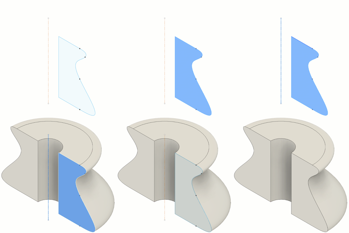
The key mental shift with Revolve is that you only need to sketch half of the object's cross-section. Fusion 360 takes care of the rest by rotating it 360 degrees.
2. Why Use Revolve? Efficiency and Editability
You could create a simple cylinder with either Extrude (a circle) or Revolve (a rectangle). But for more complex round parts, Revolve is far more efficient. Imagine creating a shape like a wine glass. Using Extrude would require multiple sketches and extrusions stacked on top of each other. With Revolve, it's just one sketch and one feature.
Let's see a practical comparison.
Learn Fusion 360 Revolve – The Best Way to Create Complex Round Parts
This video from Tyler Beck of Tech & Espresso clearly demonstrates why Revolve is superior for certain parts.
Watch the section from 00:58 to 01:59. Notice the difference in timeline complexity and ease of editing between a model made with three extrudes versus one made with a single revolve.
As the video shows, using Revolve leads to:
- A cleaner, simpler timeline, which is crucial for managing complex designs.
- Easier edits, as you only need to modify one sketch to change the entire shape, rather than editing multiple features.
This efficiency is a cornerstone of good design practice.
3. How to Use the Revolve Tool
The Revolve tool is located in the Solid tab under the Create dropdown menu. Let's break down its usage and options.
Creating Solids, Spheres, and Donuts
The most important relationship in a Revolve operation is the one between the sketch profile and the axis of revolution.
Learn Fusion 360 Revolve – The Best Way to Create Complex Round Parts
Let's continue with the same video to see how to create different shapes and use revolve options.
Watch from 01:59 to 05:08. Pay close attention to these key concepts: Sketching half a circle to create a sphere. Creating a gap between the profile and the axis to create a hole (like in a donut/torus). The core rule: Always sketch only half the profile. Revolve Options: Understanding the Type (Angle, Full) and Direction (One Side, Symmetric). These behave similarly to the options in the Extrude tool.
To summarize the key points:
- To create a solid object with no central hole, your sketch profile must be adjacent to or include the axis of revolution.
- To create an object with a central hole, simply leave a gap between your sketch profile and the axis. The size of the gap defines the radius of the hole.
Pro Tip: Using a Center Line
Fusion 360 has a special line type called a Center Line that is optimized for revolves. While you can use a regular line or a construction line as your axis, using a Center Line offers two significant advantages.
Learn Fusion 360 Revolve – The Best Way to Create Complex Round Parts
This final clip from Tyler Beck explains the benefits of using a Center Line.
Watch from 06:30 to 07:50. The video highlights two powerful benefits of using a Center Line instead of a regular or construction line.
The advantages are:
- Automatic Selection: When you activate the Revolve tool, Fusion 360 automatically recognizes the Center Line as the axis and the closed shape as the profile, saving you clicks.
- Diameter Dimensions: When dimensioning from the profile to a Center Line, Fusion 360 allows you to create a diameter dimension directly. This is extremely convenient, as you can dimension based on the final object's full diameter rather than calculating the radius for your sketch.
Using Revolve to Cut Material
Just like the Extrude tool, Revolve can be used to remove material. In the Revolve dialog, you simply change the Operation from New Body or Join to Cut. This is useful for creating grooves, internal chambers, or shaped recesses in existing parts.

4. Practice: Modeling a Simple Knob
Let's apply these concepts to model a simple, knurled knob. This is a common component in furniture, electronics enclosures, and many of your future DIY projects.
-
Start a new design and create a New Component named "Knob".
-
Create a sketch on one of the vertical origin planes (e.g., the Front/XZ plane).
-
Draw the Axis:
- Select the
Linetool. - Click on the origin and draw a vertical line upwards. Let's make it 20mm long.
- With the line still selected, click
Center Linein theLine Typesection of the Sketch Palette. The line should change style.
- Select the
-
Sketch the Profile:
- Draw the profile for half of the knob to the right of the center line. Don't worry about exact dimensions yet, just get the rough shape. It should look something like a capital "L" with a flared top.
- Use the
LineandArctools. Make sure you create a closed profile.
A rough sketch for the knob profile. The vertical line on the left is the Center Line.
-
Add Dimensions:
- Use the
Dimensiontool (Dkey). - Dimension the overall height of the knob to 15mm.
- Now, test the diameter dimensioning. Click on the outermost vertical line of your profile, then click on the center line. Move your cursor to the right, past the center line. Notice how the dimension represents the full diameter. Set the main diameter to 30mm.
- Add other dimensions to fully constrain your sketch (e.g., the bottom diameter, the height of the base, etc.).
- Use the
-
Revolve the Profile:
- Click
Finish Sketch. - Go to
Create > Revolve. - Because you used a Center Line, Fusion 360 should have automatically selected your profile and axis.
- Ensure the
OperationisNew Bodyand theAngleis360degrees. - Click OK.
- Click
You should now have a solid 3D model of a knob. Try editing your sketch and watch how the 3D model updates instantly. This is the power of parametric modeling combined with the Revolve feature.
Conclusion
Today you've added a powerful tool to your 3D modeling arsenal. You learned that for any part with rotational symmetry, Revolve is the most efficient and intelligent choice.
Key Takeaways:
- The Revolve command creates 3D solids by spinning a 2D profile around an axis.
- You only need to sketch half of the object's cross-section.
- Leaving a gap between the profile and the axis creates a central hole.
- Using a
Center Linefor your axis speeds up your workflow with auto-selection and allows for direct diameter dimensioning. - Like Extrude, Revolve can be used to
Join,Cut, or create aNew Body.
In the next lesson, we will cover the Press Pull tool. While Extrude and Revolve are for creating primary features from sketches, Press Pull is a more direct and intuitive tool for modifying existing faces on your 3D models.