Hello! Welcome to your next lesson in our "First Practical Projects" module.
In the last two lessons, you've done a great job building functional parts. You started with a phone stand that had a print-in-place hinge, teaching you about designing for motion and clearance. Then, you designed a custom holder for a gaming accessory, practicing how to model a part that fits a real-world object.
Today, we're going to combine and build on these skills. Instead of designing a part that fits an external object, you will design multiple parts that fit each other.
Today's Goal: The learning outcome for this lesson is to design and print a small storage organizer with interlocking compartments.
This project is a direct step towards your long-term goals. Modular organizers use the same principles you'll need for creating custom enclosures, multi-part assemblies for your DIY projects, and even components for your custom PC desk. We'll focus on a core technique for creating perfectly fitting 3D printed parts.
1. The Core Technique: Cut and Clearance
When you want two 3D printed parts to interlock, designing them separately and hoping they fit is difficult. A much more robust method is to design one part first, and then use that part as a "cutting tool" to create a perfectly matched negative shape in the second part.
The workflow looks like this:
- Model Part A (the "Tool").
- Model Part B, positioned to overlap with Part A.
- Use the Combine tool in a Cut operation to subtract Part A from Part B.
- Crucially, add a small clearance to the cut surfaces to ensure the 3D printed parts can actually slide together.
This technique is used across all forms of manufacturing. A classic example from woodworking is the dovetail joint. We'll study a tutorial on creating parametric dovetail joints to understand this workflow, and then adapt it for our 3D printed organizer.
Parametric Dovetail Joints in Fusion 360 – Made Easy
The following article, 'Parametric Dovetail Joints in Fusion 360', provides an excellent, detailed walkthrough of the 'cut and clearance' technique. While its focus is on woodworking, the Fusion 360 workflow is exactly what we need. Pay close attention to how one component is used to cut another.
Please read the section that starts with the heading 'We need to cut out the negative space for the tails.' It's about two-thirds of the way down the page. Focus on the use of the 'Combine' command, specifically the 'Cut' operation and the 'Keep Tools' checkbox. This is the key step we'll be using.
The article demonstrates how to create a perfect, zero-clearance fit suitable for wood. For 3D printing, we'll need to add that crucial clearance step.
2. Step-by-Step: Designing Your Interlocking Bins
Let's begin designing a simple 2x2 organizer. We'll start by modeling one bin, which will serve as our "master" component.
Step 2.1: Create the First Bin Component (The "Tool")
First, let's create a single, simple bin. It's good practice to build this as a new component.
- Create a New Component: In the toolbar, go to
Create > New Component. Name itBin_A. Make sure it is activated. - Sketch the Base: Create a sketch on the ground plane. Draw a rectangle. To make it parametric, go to
Modify > Change Parametersand create User Parameters forbin_width,bin_depth, andwall_thickness. A good starting point could bebin_width = 50mm,bin_depth = 50mm, andwall_thickness = 2mm. - Extrude the Walls: Use the
Offsettool to create an inner rectangle for the walls. Dimension the offset using yourwall_thicknessparameter. Extrude the wall profile upwards to a height you like (you can create abin_heightparameter for this, e.g.,40mm). - Sketch the Interlocking Feature: Now, let's add the "key" that will lock into the next bin.
- Create a new sketch on one of the outer faces of the bin.
- Draw a trapezoidal shape, like a simple dovetail, centered on the wall. Make its dimensions parametric as well (e.g.,
key_height,key_width,key_angle).
- Extrude the Key: Extrude this trapezoidal profile outwards from the wall. A distance of
wall_thicknessis a good choice, so it sits flush with the adjacent bin's wall.
You should now have a single bin with a key feature sticking out of one side. This is your "Tool" body.
Step 2.2: Create the Second Bin and the Cut
Now we'll create the second bin and use the first one to cut the interlocking "socket" into it.
- Activate the Top-Level Assembly: In the Browser, right-click the top-level design name and select "Activate".
- Create the Second Component: Create another new component named
Bin_B. - Model the Second Bin: Repeat the process of creating a basic bin, but this time, position it right next to
Bin_Aso that the new bin's wall overlaps the "key" you created onBin_A. - Perform the Cut: Now for the magic.
- Go to
Modify > Combine. - Target Body: Select the main body of
Bin_B. - Tool Bodies: Select the main body of
Bin_A. - Operation: Set to Cut.
- Crucially, check the "Keep Tools" box. This ensures
Bin_Aisn't deleted after the cut. - Click OK.
- Go to

If you hide Bin_A in the browser, you will now see a perfect, dovetail-shaped socket in the side of Bin_B.
Step 2.3: Adding Clearance
The socket you just created has the exact same dimensions as the key. For a 3D print, this "zero tolerance" fit will be too tight. We need to make the socket slightly larger.
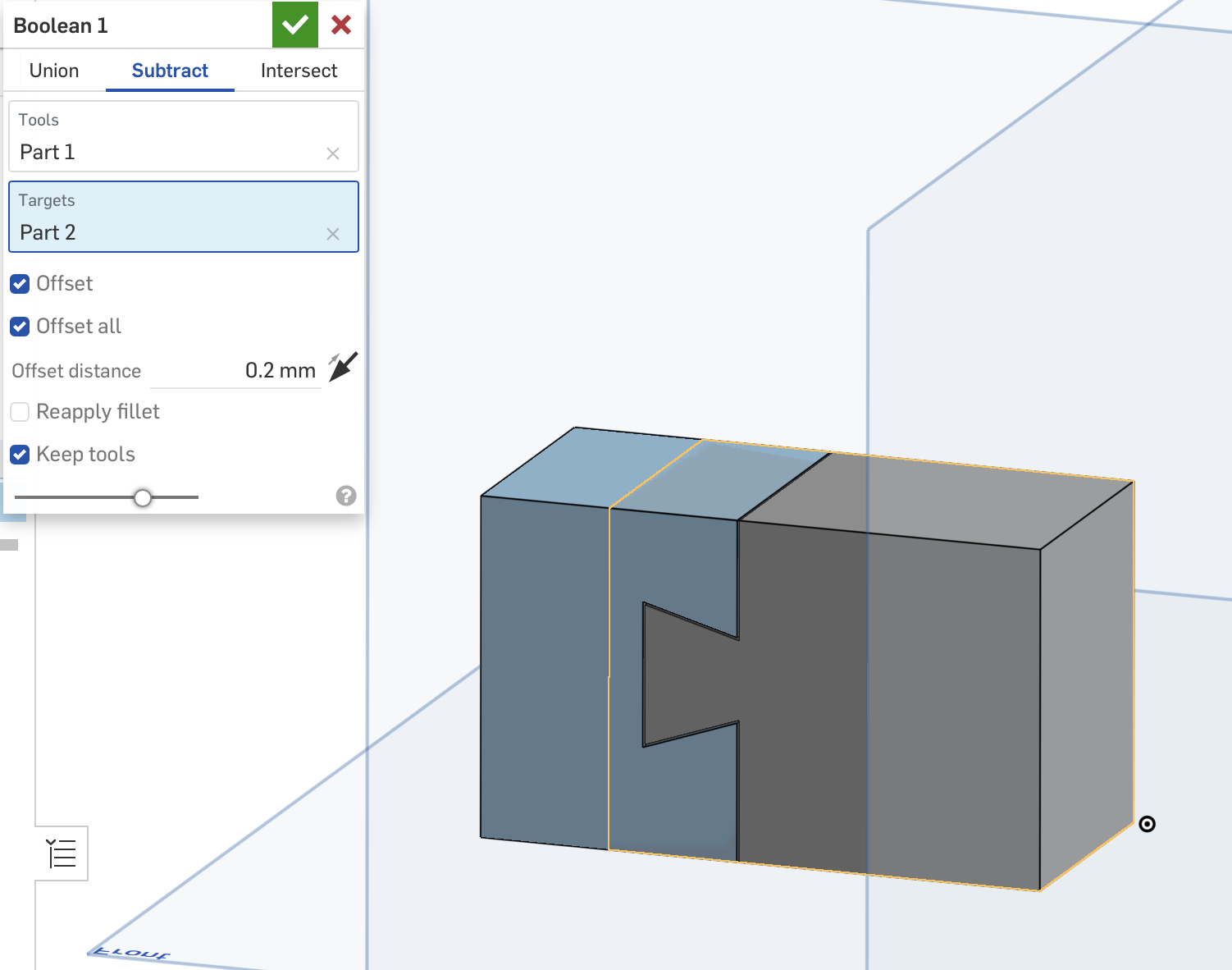
- Make sure
Bin_Bis the active component. - Activate the Press Pull tool (keyboard shortcut
Q). - Select all the internal faces of the new socket you just created in
Bin_B. - Enter a small negative value, such as
-0.2mm. This will offset each face inwards, making the socket 0.2mm larger in every direction. This0.2mmis your clearance. - Click OK.
The ideal clearance depends on your printer, filament, and desired fit (slip-fit vs. press-fit). 0.2mm is a good starting point for a slip-fit. This is something you can fine-tune as you get more experience with your printer.
3. Assembling the Full Organizer
You now have two components, Bin_A and Bin_B, that are designed to interlock perfectly. Let's create a 2x2 grid.
- Create a Mirrored Bin: We need a bin with a key on the left and a socket on the right. You can achieve this by using the Mirror command (
Create > Mirror). Set thePattern TypetoComponents, selectBin_A, and use an origin plane to mirror it. This creates a new component. - Pattern the Components: Now, use the Rectangular Pattern tool (
Create > Pattern > Rectangular Pattern).- Change the
Typeto Components. - Select the components you want to pattern.
- Select axes for the directions.
- Set the
Distanceto yourbin_widthparameter. Set the quantity to 2 (or more). Repeat for the other direction.
- Change the
You have now modeled a complete, modular, interlocking storage organizer! The parametric nature of your design means you can go back to the Parameters dialog and change the bin_width or bin_height, and the entire assembly should update automatically.
Conclusion
Fantastic work. Today's lesson was a significant step up in complexity, moving from single-body design to a multi-component, interlocking assembly. This workflow is fundamental to designing functional 3D printed objects.
Key Takeaways:
- The most reliable way to design interlocking parts is to use one component as a tool to cut the other using the
Combinecommand. - Always remember to check "Keep Tools" in the Combine dialog to preserve your original component.
- For 3D printed parts, a "perfect" digital fit is too tight. Use the Press Pull tool to add a small negative offset (e.g., -0.2mm) to create the necessary clearance.
- Designing with components and using parameters allows you to build complex, adaptable assemblies that are easy to modify.
Next Lesson Preview:
In the next lesson, we will tackle a very common and practical task: measuring a simple household object with calipers and creating a replacement part model. This will require you to apply everything you've learned so far—measuring accurately, modeling precisely, and ensuring a proper fit.