Hello! Welcome to the "Designing with Wood and Mixed Materials" module. This is an exciting step because it directly addresses the skills you'll need for your larger DIY projects, especially your goal of designing and building a custom gaming PC desk.
In our last module, we honed your ability to work with complex models, culminating in using Find in Timeline to navigate your design history efficiently. That skill will be invaluable as we begin creating assemblies with multiple wooden parts.
Today, we'll bridge the gap between the digital world of CAD and the physical world of the hardware store. Our learning outcome is to model standard wood stock dimensions and common sheet goods in Fusion 360. This means learning to create virtual pieces of lumber and plywood that accurately represent the materials you'll actually build with.
1. The First Rule of Woodworking Design: Nominal vs. Actual
Before we even open Fusion 360, we need to cover the most critical concept when designing with wood: the dimensions you see on the label are not the dimensions you get. This is the difference between nominal and actual size.
- Nominal Size: This is the name of the lumber, like a "2x4". It refers to the rough-sawn size of the board before it's dried and smoothed.
- Actual Size: This is the final dimension of the board after it has been kiln-dried (which causes shrinkage) and planed smooth on all four sides (S4S - Surfaced Four Sides).
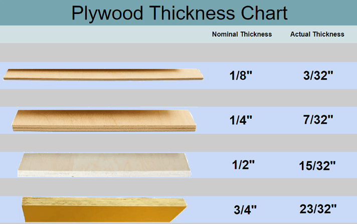
For example, a standard "2x4" in North America actually measures 1.5 inches x 3.5 inches. Modeling with the nominal size (2" x 4") will lead to significant errors in your final assembly. The same principle applies to plywood, where a "3/4 inch" sheet may be slightly thinner.
To understand this concept thoroughly, please read the following article. It provides the background on why this difference exists.
The Difference Between Nominal and Actual Boards
This article from JFR Holdings, 'The Difference Between Nominal and Actual Boards', explains the distinction and provides a helpful reference table for softwoods.
Please read the sections titled 'Nominal and Actual Sizes Defined' and 'Softwood Dimensions'. Focus on understanding why the discrepancy exists and familiarize yourself with the table of common sizes.
The image below provides a comprehensive reference chart for North American lumber sizes. This is a great resource to save for future projects.

Plywood also has a nominal vs. actual thickness. The image below provides a quick visual guide.
2. Modeling Standard Lumber and Sheet Goods
Now let's apply this in Fusion 360. The fundamental workflow for creating a piece of virtual lumber is:
- Create a New Component for the piece of wood. This keeps your project organized.
- Create a sketch of the board's cross-section using its actual dimensions.
- Use the
Extrudetool to give the board its length.
The following video from Dorset Design Build provides a clear, no-nonsense demonstration of this process for both dimensional lumber and a sheet of plywood.
Fusion 360 for Woodworking: Simple Projects
This video, 'Fusion 360 for Woodworking: Simple Projects', demonstrates the core skill of modeling standard wood stock.
Watch the two segments below. Notice how the instructor models with actual dimensions every time. Plywood Sheet (0:00 - 2:47): Watch how he creates a 4x8 foot sheet of 3/4" plywood. 2x4 Stud (2:47 - 5:50): Watch how he models a nominal 2x4 using its actual dimensions of 1.5" x 3.5".
This method is simple and effective. A key takeaway is the importance of using Components. As we move towards designing your desk, each piece of wood (each leg, the tabletop, each support beam) will be its own component, just like in a real-world assembly.
3. A More Robust Method: Using Parameters
While manually typing in dimensions works, a more powerful and flexible approach is to use Fusion 360's User Parameters. You can think of these as variables for your design.
Instead of typing "1.5in" every time you draw a 2x4's thickness, you can define a parameter named two_by_four_thickness and set its value to 1.5 inches. Then, you simply use the parameter name in your dimension fields.
Why is this better?
- Consistency: It guarantees you use the exact same dimension everywhere. No typos.
- Easy Updates: If you decide to switch from using 2x4s to 2x6s, you only need to change the parameter value in one place (
two_by_four_widthfrom 3.5in to 5.5in), and your entire model will update automatically. This is incredibly powerful for iterating on a design.
Given your background, the logic of using parameters should feel quite natural. Let's see how to set this up.
Modeling a Lumber Storage Cart - Fusion 360 for Woodworkers
The video 'Modeling a Lumber Storage Cart' by Casual Builds demonstrates a best-practice parametric workflow from the very beginning of a project.
Please watch the following two clips: Setting Up Parameters (1:16 - 3:28): Observe how the creator opens the 'Change Parameters' dialog and defines names for all the key dimensions of his project, including ply_thickness, 2by_width, and 2by_thickness. Organizing with Components (11:56 - 12:42): This short clip shows how to create new components to organize the bodies you've created based on material type (e.g., a '2x4' component).
4. Your Turn: Model Your First Pieces of Stock
Let's combine these concepts into a practical exercise. You will create a couple of standard boards using a parametric approach.
Task (15 minutes):
- Create a New Design in Fusion 360 and save it as "Wood Stock Practice".
- Set Up User Parameters:
- Go to
Modify>Change Parameters. - Click the
+next toUser Parameters. - Create the following three parameters:
- Name:
ply_thick_3_4, Expression:0.75 in - Name:
lumber_2x4_w, Expression:3.5 in - Name:
lumber_2x4_t, Expression:1.5 in
- Name:
- Click OK.
- Go to
- Model a 4-foot 2x4:
- Create a New Component and name it
2x4 Board. - Create a sketch on an origin plane (e.g., the XY plane).
- Draw a rectangle.
- When adding dimensions, instead of typing numbers, type the parameter names:
lumber_2x4_tfor the thickness andlumber_2x4_wfor the width. - Finish the sketch.
Extrudethe profile to a length of4 ft.
- Create a New Component and name it
- Model a Plywood Shelf:
- Make sure you activate the top-level component in the Browser before creating a new component. This prevents nesting.
- Create a New Component and name it
Plywood Shelf. - Create a sketch on an origin plane.
- Draw a rectangle with dimensions
2 ftby4 ft. - Finish the sketch.
Extrudethe profile. For the distance, enter the parameter nameply_thick_3_4.
You should now have a design with two separate components representing two standard pieces of wood, with their dimensions controlled by your user parameters. Try going back into the Parameters dialog and changing lumber_2x4_w to 5.5 in (the width of a 2x6) and watch your model update automatically.
Conclusion
Great work! You've just learned one of the most fundamental skills for designing real-world objects made from wood. This knowledge is the bedrock upon which we'll build your desk design.
Key Takeaways:
- Always design using actual dimensions, not nominal ones. A "2x4" is modeled as 1.5" x 3.5".
- Organize your designs by creating a new component for each individual piece of wood.
- Use User Parameters to define standard material dimensions. This makes your models robust, consistent, and easy to update.
Next Lesson Preview:
Now that we can create accurate virtual lumber, the next logical step is to join it together. In our next lesson, we will explore how to design and model common subtractive wood joints, starting with the butt joint, rabbet, and dado. This will be our first step into creating assemblies.