Hello! Welcome to the next lesson in our course on bare-metal driver development.
In the last lesson, we mastered the SysTick timer, using it to create a precise, periodic interrupt for system time-basing. That was an excellent exercise in using a simple, core-level timer. Today, we take a significant step forward. We're moving from generating a simple interrupt "tick" to creating a structured, controllable waveform.
Our goal is to develop a timer driver to generate a PWM signal with a configurable frequency and duty cycle. Pulse Width Modulation (PWM) is a cornerstone of embedded control systems, used for everything from dimming LEDs and controlling the speed of DC motors to sophisticated power conversion in electric vehicles. Your background in automotive systems gives you context for its importance, and mastering its low-level implementation is a key skill for any embedded driver developer.
1. What is PWM?
At its heart, PWM is a technique for controlling the average power delivered to a load by switching a digital signal ON and OFF at a high frequency. Two parameters define the signal:
- Frequency: How often the signal repeats its ON/OFF cycle. This is determined by the signal's period (). .
- Duty Cycle: The percentage of time the signal is in the HIGH state within one period. A 100% duty cycle means the signal is always HIGH, while a 0% duty cycle means it's always LOW.
For a clear definition of these core concepts, please read the introductory section of the following article from DeepBlueEmbedded.
Read the sections 'PWM Frequency', 'PWM Duty Cycle', and 'PWM Resolution'. Pay attention to the formulas and the interactive tool, which provides a great feel for how duty cycle affects the average voltage.
2. Generating PWM with a General-Purpose Timer
While the SysTick timer was great for periodic interrupts, it's too simple for PWM generation. For this, we use a general-purpose timer peripheral. These are more complex and powerful, designed with dedicated hardware for tasks like PWM.
To understand how they work, it's helpful to think of the timer as being composed of three key submodules, a concept well-articulated in professional-grade peripheral manuals.
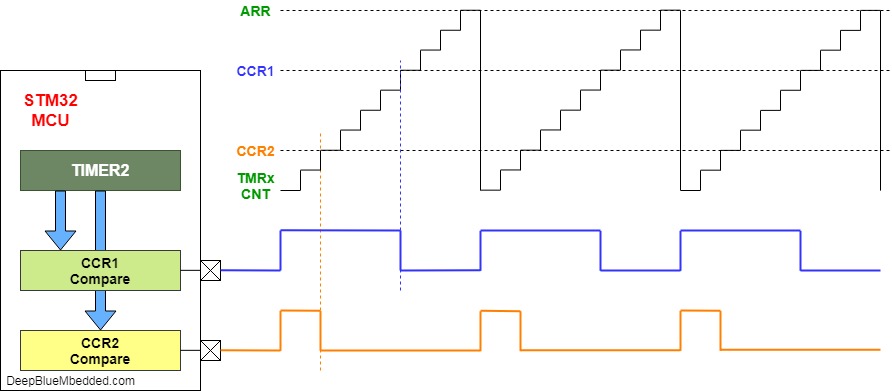
Let's break down the roles of the submodules:
-
Time-Base (TB) Submodule: This is the heart of the timer. Its job is to generate the fundamental timing for our PWM signal, which dictates the frequency.
- Counter (CNT): A register that increments at a specific rate.
- Prescaler (PSC): A divider that slows down the main system clock before it reaches the counter. This allows us to generate a wide range of frequencies. The counter increments every
(PSC + 1)clock cycles. - Auto-Reload Register (ARR or TBPRD): This register holds the maximum value the counter will reach. When the counter hits the ARR value, it resets to 0, completing one PWM period.
The PWM frequency is therefore calculated as:
where is the peripheral clock frequency feeding the timer. -
Counter-Compare (CC) Submodule: This submodule is responsible for defining the duty cycle.
- Capture/Compare Register (CCRx or CMPx): This register holds a value that is continuously compared against the main timer counter (CNT). When
CNT == CCRx, the submodule generates a "compare match" event.
- Capture/Compare Register (CCRx or CMPx): This register holds a value that is continuously compared against the main timer counter (CNT). When
-
Action-Qualifier (AQ) Submodule: This is where the logic happens. It takes events from the TB submodule (e.g., "counter hit zero," "counter hit ARR") and the CC submodule (e.g., "compare match occurred") and translates them into actions on the physical output pin (e.g., "set pin HIGH," "set pin LOW").
By configuring the AQ submodule correctly, we can create a PWM signal. A very common configuration ("PWM Mode 1") is:
- Action on
CNTreaching 0: Set the output pin HIGH. - Action on
CNTmatchingCCRx: Set the output pin LOW.
The result? The pin is HIGH from the start of the period until the compare match, and LOW for the rest of the period. The duty cycle is thus directly proportional to the CCRx value.
\text{Duty Cycle (%)} = \frac{CCRx}{ARR + 1} \times 100
Test your understanding!
You have a timer with its ARR set to 999 and its PSC set to 1. The input clock is 72 MHz.
- What is the frequency of the resulting PWM signal?
- What value would you write to the CCRx register to achieve a 25% duty cycle?
Show answer
- Frequency:
- CCRx for 25% Duty Cycle:
Since duty cycle isCCRx / (ARR + 1), we haveCCRx = Duty Cycle * (ARR + 1).
You would write 250 to the CCRx register.
3. Developing the PWM Driver
Now, let's structure our C driver. The goal is to create functions that abstract away the register-level details, allowing a user to simply request a PWM signal of a certain frequency and duty cycle.
Driver Structure
A minimal PWM driver would have two main functions:
void PWM_Init(TIM_TypeDef* timer, uint8_t channel, uint32_t frequency, float duty_cycle): Configures a specific timer channel for PWM output.void PWM_SetDutyCycle(TIM_TypeDef* timer, uint8_t channel, float duty_cycle): Updates the duty cycle of an already-initialized PWM channel.
Implementation Steps for PWM_Init
Let's walk through the steps needed inside the initialization function. We'll use register names common to STM32 microcontrollers, as they are widely used and serve as a good example.
- Enable Clocks: Enable the peripheral clock for the chosen timer (e.g.,
TIM2) and the corresponding GPIO port. - Configure GPIO Pin: Set the pin to its "Alternate Function" mode so the timer peripheral can control it. This mapping is found in the microcontroller's datasheet.
- Calculate PSC and ARR: This is the trickiest part. We have one equation for frequency and two variables (
PSCandARR). A common strategy is to fix one and solve for the other. For high resolution (more steps for duty cycle), we want a largeARR. Let's assume we aim for anARRvalue around 10000.PSC = (f_clock / (f_pwm * ARR_target)) - 1- Recalculate
ARRwith the chosenPSCfor precision:ARR = (f_clock / (f_pwm * (PSC + 1))) - 1
- Configure the Time-Base:
- Write the calculated values to the timer's
PSCandARRregisters. - Set the counter direction to up-counting mode (
TIMx->CR1).
- Write the calculated values to the timer's
- Calculate the Compare Value:
uint32_t ccr_value = (duty_cycle / 100.0) * (TIMx->ARR + 1);
- Configure the Output Compare Channel:
- Set the channel to PWM Mode 1 (
TIMx->CCMRy). - Enable the output channel (
TIMx->CCER). - Write
ccr_valueto the correspondingTIMx->CCRyregister.
- Set the channel to PWM Mode 1 (
- Enable the Timer:
- Set the UG bit in
TIMx->EGRto generate an update event, which loads the prescaler and ARR values from their shadow registers. - Set the main counter enable bit (
CEN) inTIMx->CR1.
- Set the UG bit in
Implementation for PWM_SetDutyCycle
This is much simpler. The frequency is already set by PSC and ARR. We only need to update the CCR value.
void PWM_SetDutyCycle(TIM_TypeDef* timer, uint8_t channel, float duty_cycle) {
    if (duty_cycle < 0.0f) duty_cycle = 0.0f;
    if (duty_cycle > 100.0f) duty_cycle = 100.0f;

    uint32_t ccr_value = (duty_cycle / 100.0f) * (timer->ARR + 1);

    switch(channel) {
        case 1: timer->CCR1 = ccr_value; break;
        case 2: timer->CCR2 = ccr_value; break;
        // ... and so on for other channels
    }
}
4. A Practical Walkthrough
Theory and register maps are essential, but seeing it come together in a real project is invaluable. The following video demonstrates building a PWM driver from scratch. The microcontroller is a TI MSP430, so the register names are different, but the fundamental logic is exactly what we just discussed.
Motor Control with PWM in C | Embedded System Project Series #21
This video from Artful Bytes shows the end-to-end process of creating a PWM driver to control a motor. Pay close attention to how the developer reasons about the timer configuration.
Watch the following segments carefully: 04:48 - 09:23: Focus on the logic for choosing the timer frequency (20kHz) and how the base period is calculated. He cleverly sets the period to 100 ticks, which simplifies the duty cycle calculation later. This is a perfect example of applying our frequency formula. 09:23 - 11:00: Observe how he calculates the timer's input divider to achieve the desired tick rate from the main system clock. This is the practical application of setting the PSC register. 15:54 - 18:20: This is the core of the set_duty_cycle function. Notice how, because the period is 100, he can almost directly use the percentage value for the compare register. Also, see the power-saving logic to disable the timer when the duty cycle is zero.
This practical approach highlights a key engineering trade-off: you can choose your timer parameters (PSC, ARR) strategically to make other parts of your code, like the duty cycle calculation, simpler and more efficient.
Interview Preparation
-
Question: "Walk me through how you would configure a hardware timer to generate a 10 kHz PWM signal with a 75% duty cycle on a microcontroller running at 84 MHz."
- Your Answer: "First, I'd determine the prescaler (PSC) and auto-reload (ARR) values. To maintain good resolution, I'd target an ARR value, say 999. The equation is
f_pwm = f_clk / ((PSC+1)*(ARR+1)). Solving for PSC:(PSC+1) = 84M / (10k * 1000) = 8.4. I'd choose the nearest integer, soPSC = 7. WithPSC=7, I'd re-calculate the exact ARR:(ARR+1) = 84M / (10k * 8) = 1050, soARR = 1049. I'd write 7 to the PSC register and 1049 to the ARR register. For the duty cycle, the compare register (CCR) value would be0.75 * (1049 + 1) = 787.5. I'd write 787 or 788 to the CCR. Finally, I'd configure the timer in PWM mode, enable the output channel, and start the counter."
- Your Answer: "First, I'd determine the prescaler (PSC) and auto-reload (ARR) values. To maintain good resolution, I'd target an ARR value, say 999. The equation is
-
Question: "What is the trade-off between PWM frequency and resolution?"
- Your Answer: "They are inversely proportional. The resolution is determined by the number of steps the counter takes in one period, which is set by the ARR value. From the frequency formula,
(ARR+1) = f_clk / (f_pwm * (PSC+1)). To increase the frequency, you must decrease either ARR or PSC. If you decrease ARR, you reduce the number of discrete steps available for the duty cycle, thus lowering the resolution. For example, generating a 1 MHz PWM from a 100 MHz clock gives you only 100 steps of resolution (ARR=99), whereas a 10 kHz PWM could have 10,000 steps (ARR=9999)."
- Your Answer: "They are inversely proportional. The resolution is determined by the number of steps the counter takes in one period, which is set by the ARR value. From the frequency formula,
-
Question: "You have a running PWM signal controlling a motor's speed. How do you update the speed (duty cycle) without causing glitches? What hardware feature helps with this?"
- Your Answer: "To update the duty cycle, I would simply calculate the new compare value and write it to the appropriate CCRx register. To prevent glitches, most advanced timers use shadow registers. When I write to the CCRx memory address, I'm actually writing to a buffered shadow register. The hardware is designed to automatically transfer the value from the shadow register to the active register at a safe point in the PWM cycle, typically when the counter resets to zero (an update event). This ensures the new duty cycle takes effect cleanly at the start of a new period, preventing pulses of incorrect width."
Conclusion
Today we've demystified PWM generation. We've seen how the intricate dance between the Time-Base, Counter-Compare, and Action-Qualifier submodules of a general-purpose timer allows us to create highly configurable waveforms.
Key Takeaways:
- PWM is defined by its frequency and duty cycle.
- The timer's Prescaler (PSC) and Auto-Reload Register (ARR) control the frequency.
- The Capture/Compare Register (CCRx) controls the duty cycle.
- A robust driver involves calculating these register values based on user inputs and configuring the timer's output mode correctly.
- Runtime changes to the duty cycle are made by updating the
CCRxregister, and shadow registers ensure this happens smoothly.
Next Lesson Preview:
We've now covered timing peripherals for both periodic events (SysTick) and waveform generation (PWM). Next, we will shift our focus to communication. You will develop an interrupt-driven UART driver using circular buffers for robust serial communication. This will introduce new challenges related to handling asynchronous data reception and managing data buffers efficiently, another critical skill set for embedded systems interviews.