Hello! Welcome to our next lesson.
In the previous session, we successfully configured the microcontroller's clock system, bringing it up to its maximum operational speed using the external crystal and PLL. We also saw how to enable clocks for individual peripherals using clock gating. This is the essential foundation for everything that follows.
Today, we will build on that foundation to explore one of the most versatile and crucial peripherals in any microcontroller: the general-purpose timer. Our learning outcome is to explain the architecture of a general-purpose timer and its common modes (e.g., periodic, input capture, PWM).
Your experience with AUTOSAR's GPT (General Purpose Timer) module has given you a high-level view of what timers do. This lesson will peel back that abstraction, revealing the underlying hardware registers and logic that make it all possible. A deep understanding of timers is non-negotiable for low-level driver development and is a very common topic in technical interviews.
1. The Fundamental Components of a Timer
At its heart, a timer is simply a digital counter. However, a modern microcontroller timer is much more than that. It's a sophisticated peripheral with several key components that work in concert.
Let's start with a video that introduces the basic concepts of a timer's core components: the clock source, the prescaler, and the counter.
Getting Started with STM32 and Nucleo Part 6: Timers and Timer Interrupts | Digi-Key Electronics
This video from Digi-Key provides an excellent, concise introduction to why timers are important and the role of the prescaler and the counter.
Please watch the first 1 minute and 24 seconds. Focus on understanding how the prescaler divides the main system clock to create a slower 'tick' for the timer's counter.
To summarize and expand on the video, every general-purpose timer is built around these core components:
- Clock Source: This is the input to the timer, typically derived from one of the system's bus clocks (like APB1 or APB2) that we configured in the last lesson.
- Prescaler (PSC): A programmable divider that slows down the input clock. If your system clock is 84 MHz, counting every clock cycle makes it difficult to measure longer time intervals. By setting the prescaler, you can control the timer's resolution. For example, with a prescaler of 8400, the timer counter will increment every ms.
- Counter (CNT): This is the main register that increments (or decrements) at the rate of the prescaled clock. It's typically a 16-bit or 32-bit register.
- Auto-Reload Register (ARR): This register holds the value at which the counter will either reset to 0 (in up-counting mode) or trigger an event. The value in the ARR determines the timer's period. When the counter reaches the ARR value, it generates an update event and, if configured, an interrupt.
This combination of PSC, CNT, and ARR forms the timer's time-base unit.
2. Architecture of a General-Purpose Timer
While basic timers might only have a time-base unit, general-purpose timers add more features, primarily through input/output channels.
STM32 Timers Tutorial | Hardware Timers Explained
This article from DeepBlue Embedded provides an excellent breakdown of the different types of timers found in STM32 microcontrollers and their features. We'll focus on the general-purpose timer.
Please read the section '2. STM32 Timers Hardware', focusing specifically on the subsection '2.3 General-Purpose Timers Modules'. This will give you an overview of the features that distinguish a general-purpose timer from a basic one.
The key addition in a general-purpose timer is a set of Capture/Compare Registers (CCR), one for each channel. These registers are central to the timer's advanced modes. Depending on the mode, a CCR can:
- Capture: Store the value of the counter (CNT) when an event occurs on an input pin.
- Compare: Continuously compare its value against the counter (CNT) and trigger an action on an output pin when they match.
Let's look at a detailed block diagram to see how these pieces fit together.

Notice the data paths. The time-base unit (CNT, PSC, ARR) runs independently. The channels work in parallel, either monitoring external pins to capture the CNT value or comparing the CNT value to affect the state of an external pin.
3. Common Timer Modes of Operation
Now, let's explore how these architectural components are used to implement the most common timer modes.
STM32 Timers Tutorial | Hardware Timers Explained
The DeepBlue Embedded article also has a great summary of the different operational modes. This will serve as our guide.
Please read section '3. STM32 Timers Modes OF Operation', paying close attention to the descriptions for 'Timer Mode', 'Input Capture Mode', and 'PWM Mode'. We will explore these three in more detail.
a. Periodic Timer Mode (Update Interrupt)
This is the simplest and most common mode.
- How it works: The counter (CNT) increments at the prescaled clock frequency. When it reaches the value stored in the auto-reload register (ARR), it resets to 0 and generates an update event. If enabled in the Nested Vectored Interrupt Controller (NVIC), this event triggers an interrupt.
- Purpose: To execute a piece of code at a fixed interval. This is the foundation for creating a system "tick" for an RTOS, running periodic sensor checks, or creating non-blocking delays.
- Key Registers:
PSC,CNT,ARR.
This is the mode we will use in our next lesson to implement the SysTick driver.
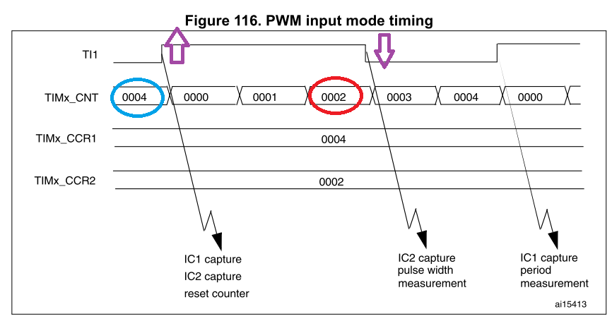
b. Input Capture Mode
This mode is used to measure the timing of external signals.
- How it works: An external signal is connected to a timer channel input pin. When a specified edge (rising, falling, or both) is detected on that pin, the current value of the counter (CNT) is copied—or "captured"—into the corresponding Capture/Compare Register (CCR). An interrupt can be generated on this capture event. By capturing the timer values at two consecutive events, you can calculate the time elapsed between them.
- Purpose: To measure frequency, period, or pulse width of an input signal. For example, measuring the pulse width from an ultrasonic sensor to determine distance, or decoding signals from an infrared remote.
- Key Registers:
PSC,CNT,CCR(in capture mode).
c. Pulse Width Modulation (PWM) Mode
This mode is used to generate a digital signal with a variable duty cycle.
- How it works: In PWM mode, the timer operates in a combination of periodic and output compare functionality. The ARR register sets the period of the PWM signal. The CCR register sets the duty cycle. The timer counts from 0 to ARR. The output pin is set high when the timer starts and is set low when the counter value matches the CCR value.
- Purpose: Essential for controlling analog-like behavior with a digital signal. Common applications include controlling the brightness of an LED, setting the speed of a DC motor, or controlling the position of a servo motor.
- Key Registers:
PSC,CNT,ARR(for period),CCR(for duty cycle/pulse width).
Test your understanding!
You are tasked with designing a simple dimmable LED driver. You need to control the LED's brightness from 0% to 100%. Which timer mode would you use, and which two registers would be most important for controlling the PWM signal's frequency and brightness level, respectively?
Show answer
You would use PWM Mode.
- The Auto-Reload Register (ARR) would control the PWM frequency (the period of the signal).
- The Capture/Compare Register (CCR) would control the brightness level (the duty cycle or pulse width). By changing the CCR value relative to the ARR value, you change the percentage of time the signal is high, thus dimming the LED.
4. A Broader View: The ARM Generic Timer
While the timers we've discussed are vendor-specific peripherals (like those in STM32 or NXP devices), the ARM architecture itself defines a standard timer framework known as the ARM Generic Timer. This is particularly relevant for higher-end Cortex-A and Cortex-R processors and is an important concept for advanced roles.
The Generic Timer is architecturally different from a peripheral timer:
- It consists of a single, always-on System Counter that provides a common time reference for all cores in a multi-core system.
- Each core has a set of private comparators. Software configures a comparator with a future value. When the system count matches this value, the comparator triggers a private interrupt to its core.
AArch64 Programmer's Guide: Generic Timer
To understand this architectural feature, let's review the programmer's guide from ARM. We will focus on the high-level concepts.
Please read section 2, 'What is the Generic Timer?', and section 3.3, 'Configuring a timer'. Focus on the conceptual difference: a shared System Counter vs. per-core timers that are just comparators. Also, pay attention to the two programming models described: using CVAL (absolute time) and TVAL (relative time).
The key takeaway is that there are two main types of timers you'll encounter:
- Peripheral Timers: Highly versatile, I/O-focused peripherals with many modes (Input Capture, PWM, etc.). These are what you use for most driver-level tasks.
- ARM Generic Timer: An architectural feature primarily used by the operating system for scheduling and providing a consistent view of time across the system. It's less about I/O and more about core-level timekeeping.
Interview Preparation
-
Question: "Can you describe the core components of a general-purpose timer peripheral and how they work together to create a periodic interrupt?"
- Your Answer: "A general-purpose timer's core is its time-base unit, consisting of a clock source, a prescaler (PSC), a counter (CNT), and an auto-reload register (ARR). The input clock is divided by the prescaler to set the timer's resolution. The counter increments at this prescaled rate. The ARR defines the period. When the counter value reaches the ARR value, it overflows, resets to zero, and generates an update event, which can be configured to trigger a periodic interrupt."
-
Question: "You need to measure the frequency of an unknown square wave signal. Which timer mode would you use, and how would it work at a high level?"
- Your Answer: "I would use Input Capture mode. I'd configure a timer channel to trigger on the rising edge of the input signal. On the first rising edge, the timer captures the counter value. On the second rising edge, it captures the value again. The difference between these two captured values, multiplied by the timer's tick period, gives me the period of the signal. The frequency is then simply the inverse of that period."
-
Question: "Explain how a timer is configured to generate a PWM signal. Which registers are primarily involved in setting the frequency and duty cycle?"
- Your Answer: "To generate a PWM signal, the timer is configured in PWM mode. The Auto-Reload Register (ARR) determines the period of the counter's cycle, which sets the PWM frequency. A Capture/Compare Register (CCR) is used to set the pulse width. The output is active for the portion of the period where the counter is less than the CCR value. So, ARR controls the frequency, and CCR controls the duty cycle."
-
Question: "What is the difference between a peripheral timer, like you'd find on an STM32, and the ARM Generic Timer?"
- Your Answer: "A peripheral timer is a vendor-specific hardware block with extensive features for I/O operations like PWM generation, input capture, and encoder interfacing. The ARM Generic Timer, on the other hand, is part of the core ARM architecture itself. It's designed to provide a standardized, system-wide time base, primarily for the operating system's use, such as for task scheduling. It consists of a shared system counter and per-core comparators that trigger interrupts, rather than a versatile I/O-focused peripheral."
Conclusion
Today we've taken a deep dive into the architecture of general-purpose timers. You've learned about the fundamental building blocks and how they are orchestrated to create powerful and versatile modes of operation.
Key Takeaways:
- A timer's core is the time-base unit: a clock source, prescaler (PSC), counter (CNT), and auto-reload register (ARR).
- General-purpose timers add Capture/Compare Registers (CCR) for advanced I/O functionality.
- Periodic Mode uses the ARR to generate interrupts at fixed intervals.
- Input Capture Mode uses a CCR to timestamp external events, allowing measurement of signals.
- PWM Mode uses the ARR for frequency and a CCR for duty cycle to generate variable-pulse signals.
- The ARM Generic Timer is an architectural feature for OS-level timekeeping, distinct from vendor-specific peripheral timers.
Next Lesson Preview:
Now that you have a solid theoretical understanding of the periodic timer mode, we will put it into practice. In the next lesson, we will implement a driver for the SysTick timer to generate periodic interrupts for time-basing. The SysTick is a special, simplified timer built into every ARM Cortex-M core, and it is the standard choice for generating the system tick for an RTOS.