In our previous lesson, we established the first half of the "most severe coincident condition" by determining the design pressure. We saw that it's not just the operating pressure, but a carefully considered value that accounts for static head and potential pressure variations. Now, we turn our attention to the other critical variable in this pair: the design temperature.
This lesson focuses on determining the appropriate design temperature for a piping system according to ASME B31.3, Paragraph 301.3. Your background in mechanical engineering provides a solid understanding of how temperature affects material properties, particularly strength. We will translate that fundamental knowledge into the specific rules and practices mandated by the code, including how to estimate the actual pipe metal temperature, which can differ significantly from the process fluid temperature.
Fluid Temperature vs. Metal Temperature
The first and most crucial distinction the code makes is between the temperature of the fluid flowing inside the pipe and the temperature of the pipe metal itself. The allowable stress of a material, which is the cornerstone of pressure design, is a direct function of its temperature. Therefore, the design temperature is the metal temperature expected in service.
Several factors can cause the pipe metal temperature to be different from the fluid temperature:
- Insulation: If a pipe is well-insulated, heat loss to the environment is minimized, and the metal temperature will be very close to the fluid temperature.
- Ambient Conditions: An uninsulated pipe will lose heat to (or gain heat from) the surrounding air. An uninsulated pipe carrying a hot fluid will have a metal temperature somewhat lower than the fluid temperature.
- Solar Radiation: A pipe exposed to direct sunlight will absorb radiant heat, potentially raising its metal temperature above the ambient temperature, even if the fluid inside is cool.
- Heat Tracing: Often, pipes are externally heated (e.g., with steam or electric tracing) to prevent a fluid from freezing or to maintain viscosity. In this case, the metal temperature can be significantly influenced by the tracing system.
The designer is responsible for considering all these effects to arrive at a realistic metal temperature for the component.
Rules for Determining Design Temperature
ASME B31.3 provides specific guidance for estimating the metal temperature. The resource below, an excerpt from a guide on piping design, details these rules.
Schedule 40 Pipe - an overview | ScienceDirect Topics
This text explains the requirements of B31.3 Para. 301.3 for establishing design temperature, covering various scenarios for insulated and uninsulated piping.
Please read section 2.3.6.3, "Design temperature (B31.3 §301.3)". Pay close attention to the following points: The general factors to consider, outlined in the initial paragraph. The rules for uninsulated components operating at higher temperatures, which allow for a reduction based on component type. Note the values in Table 2.9.
As you read, the rules can be summarized as follows:
- Insulated Pipe: The design temperature is taken as the fluid temperature, unless external heating (like heat tracing) would result in a higher temperature.
- Uninsulated Pipe, Fluid Temp < 65°C (150°F): The design temperature is taken as the fluid temperature, unless effects like solar radiation would cause a higher temperature. A common practice is to assume a metal temperature of 50°C (120°F) for pipes exposed to the sun if this is more severe than the fluid temperature.
- Uninsulated Pipe, Fluid Temp ≥ 65°C (150°F): Here, the code acknowledges that convective cooling to the ambient air will lower the metal temperature. It permits the design temperature for uninsulated components to be a percentage of the fluid temperature, as shown in the table from the reading.
A Practical Example
Your preference for calculation-heavy learning will be well-served here. Let's apply these percentage rules to a common scenario.
Problem:
A segment of an uninsulated piping system is made from ASTM A106 Grade B carbon steel. It carries superheated steam at a steady operating temperature of 400°C. The system includes straight pipe, standard weld fittings, and ASME B16.5 weld neck flanges with ASTM A193 B7 bolts. What are the design temperatures for the pipe, the flanges, and the bolts?
Solution:
Since the fluid temperature (400°C) is above 65°C, we can use the percentages from Table 2.9 in the reading you just completed.
-
Pipe and Welded Fittings: These components have a wall thickness comparable to the pipe.
- Design Temperature = 95% of Fluid Temperature
-
Flanges (Weld Neck):
- Design Temperature = 90% of Fluid Temperature
-
Bolts: Bolts are further from the hot fluid and receive significant cooling from ambient air.
- Design Temperature = 80% of Fluid Temperature
This example demonstrates why you cannot simply use the fluid temperature for all components. Using a lower, more realistic design temperature for the flanges and bolts may allow for the use of a lower-rated (and less expensive) component, while still being fully compliant and safe.
Design Minimum Temperature
Just as we must consider the highest temperature for material strength, we must also consider the lowest temperature to assess the risk of brittle fracture. The design minimum temperature is the lowest metal temperature a component will experience during service. This could be due to low ambient conditions, process upsets, or autorefrigeration (the rapid cooling that occurs when a pressurized liquid or gas is depressurized, also known as the Joule-Thomson effect).
ASME B31.3 specifies a minimum temperature for most materials listed in its allowable stress tables, below which the material's toughness must be proven through impact testing (e.g., Charpy V-notch test).
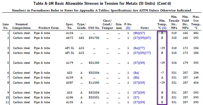
Look at the table above. For the material on Line 3 (API 5L A25), the minimum temperature is -29°C. This means if the design minimum temperature for a system using this pipe is, for example, -20°C, no impact testing is required by default. However, if the service could expose it to -40°C, its suitability must be verified according to the code's low-temperature toughness rules (Para. 323). The "B" in that column refers to Note B of Para. 323.2.2, which sets the specific conditions for exemption from impact testing. As an experienced inspector, you know the importance of material traceability and verifying that the correct material has been used for the design conditions. This is where that requirement originates.
A Note on Variations
Finally, it's important to recognize that, similar to pressure, the code allows for short-term variations above the design temperature. Paragraph 302.2.4, which we will study in detail in a later module on occasional loads, permits the temperature to exceed the design value for a limited number of hours and by a certain percentage, provided several criteria are met (e.g., the material is ductile). This prevents the need to design an entire system for a rare, short-lived upset condition, which would be overly conservative and expensive.
Conclusion
This lesson has equipped you to determine the second crucial parameter for pressure design: the design temperature. You now understand how to translate process fluid conditions into the specific metal design temperatures required by ASME B31.3.
Here are the key takeaways:
- The design temperature is the pipe metal temperature, which is not always the same as the fluid temperature.
- For insulated pipes, the metal temperature is typically taken as the fluid temperature.
- For uninsulated pipes, the code provides specific rules, including percentage-based reductions for high-temperature service to account for ambient cooling.
- The design minimum temperature is equally important and is used to assess the material's resistance to brittle fracture.
- The code provides tables (like Table A-1) that list minimum temperatures for materials, indicating the threshold for requiring impact testing.
With the design pressure and temperature established, we have defined the fundamental operating envelope for the piping system. This envelope dictates the material's inherent strength (its allowable stress). The next logical step is to quantify the forces and moments—the loads—that will act on the piping. In our next lesson, we will classify these loads into sustained, occasional, and displacement categories, which form the basis for all stress analysis calculations.