Hello! Welcome to your next lesson in two-dimensional kinematics.
In our last lesson, we derived the key formulas for maximum height, time of flight, and horizontal range. A critical assumption we made was that the projectile lands at the same height from which it was launched. Today, we will remove that constraint and tackle a more general and challenging scenario that is a staple of advanced physics problems.
Our learning outcome is to solve projectile motion problems on an inclined plane by decomposing motion in an optimally chosen coordinate system. You will see that a clever choice of axes can transform a complex problem into a familiar one. This lesson emphasizes strategy and mathematical rigor over rote memorization, which will be crucial for the JEE Advanced and Olympiad-level problems you're aiming for.
1. The Challenge of the Incline and the Power of Coordinates
Imagine a projectile launched with speed at an angle to the horizontal, from the base of a plane inclined at an angle .
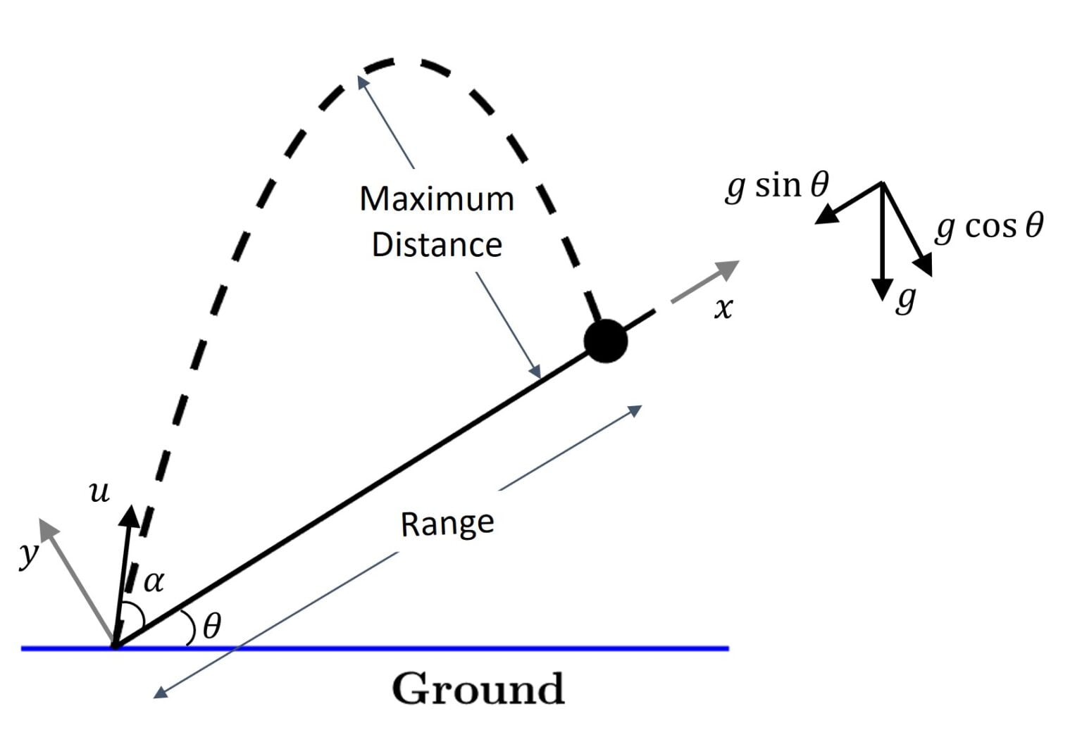
We have two primary ways to set up our coordinate system:
- Standard System: The x-axis is horizontal, and the y-axis is vertical. Here, the acceleration due to gravity is simple (), but the landing condition is complicated: the projectile lands on the line .
- Tilted System: The x-axis is parallel to the incline, and the y-axis is perpendicular to it. Here, the landing condition becomes simple (the projectile lands when its y-coordinate is zero), but the acceleration due to gravity must be decomposed into components in this new system.
For most problems, the Tilted System is more efficient. Let's explore why by deriving the key parameters using both methods.
This document provides a concise and rigorous comparison of the two coordinate systems for solving this exact problem. It will form the mathematical backbone of our analysis.
Please read the document from the beginning down to the 'Moral' on page 2. Focus on understanding the setup for Choice (I) (Standard System) and Choice (II) (Tilted System). Follow the derivations for the time of flight and the distance 'd' (which we call Range, R) for both cases. Note how the simplicity of the landing condition (y=0) in Choice (II) makes the derivation more straightforward.
As you've seen in the reading, while both methods yield the same result, the tilted coordinate system (Choice II) makes the process significantly more systematic. The motion perpendicular to the incline becomes analogous to standard vertical motion, allowing us to find the time of flight easily.
2. Deep Dive: Derivation in the Tilted Frame
Let's formalize the derivation using the tilted coordinate system, which is the "optimal" choice for this class of problems. We'll denote the tilted axes as and .
Step 1: Decompose Acceleration and Initial Velocity
As seen in the diagram above, the gravitational acceleration is resolved into components along and perpendicular to the incline:
- Acceleration along -axis:
- Acceleration along -axis:
The initial velocity is launched at an angle to the horizontal. Its angle with respect to the incline is . The components in the tilted frame are:
- Initial velocity along -axis:
- Initial velocity along -axis:
Step 2: Find the Time of Flight (T)
The projectile lands on the incline when its displacement perpendicular to the incline is zero, i.e., .
Using the equation of motion :
Factoring out and taking the non-zero solution gives us the time of flight:
Step 3: Find the Range along the Incline (R)
The range is the displacement along the incline, .
Using :
Substituting the expression for and performing the algebraic simplification (as shown in the resource LINK), we arrive at the final expression for the range:
These are general formulas, but your goal should be to understand the derivation method so you can apply it to any situation, rather than memorizing the formulas themselves.
Test your understanding!
A particle is projected from the bottom of an inclined plane of inclination . The initial velocity is at an angle of with the horizontal. Find the time of flight and the range along the incline. (Use ).
Show answer
Here we have: , , .
The angle of projection with respect to the incline is .
Time of Flight:
Range:
3. Maximizing the Range: A Deeper Look
A classic problem is to find the launch angle that gives the maximum range up the incline for a fixed initial speed . One could use calculus and set , but there's a more elegant method.
Let's return to the document 'Projectile motion'. The author provides a clever trigonometric simplification to find the maximum range without using calculus.
Please read section (b) on page 2. Pay close attention to how the expression for 'd' is rewritten using the product-to-sum identity sin(A)cos(B) = 1/2[sin(A+B) + sin(A-B)]. This manipulation directly reveals the condition for maximizing the range.
As the derivation shows, the range is maximized when , which means . This gives the optimal launch angle:
This result has a beautiful geometric interpretation. The optimal launch velocity vector bisects the angle between the incline and the vertical.
For an even deeper, proof-based perspective that you appreciate, this result can be derived using pure geometry related to the focus-directrix property of a parabola.
This Olympiad-level handout from Kevin Zhou offers a powerful geometric proof. It connects the maximum range problem to the fundamental properties of parabolas.
First, read Problem 31, which states the problem of maximizing the range and gives the calculus-based solution. Then, read the solution to Problem 34(c), which re-derives the same result using the focus and directrix of the 'parabola of safety'. This geometric method is extremely powerful and provides a profound insight into why the angle bisector rule works.
This geometric viewpoint is not just a curiosity; it's a powerful tool that we will develop further in our next module.
4. Advanced Application: A JEE-Level Problem
Let's now see how to apply these principles to a complex problem typical of the JEE Advanced. The problem involves conditions beyond just landing on a plane, such as grazing a surface or hitting another surface normally.
Advance Illustrations - Projectile Between Inclined Planks | Kinematics #31 for JEE Advanced
This video from Physics Galaxy solves a challenging problem involving a projectile between two inclined planks. It's a perfect example of applying the tilted coordinate system method under multiple constraints.
Watch the entire video (up to 06:41). Focus on these key steps: How the problem is set up in an inclined reference frame. How the conditions of 'grazing' one plank and 'hitting the other normally' are translated into kinematic equations. How these equations are solved simultaneously to find the required angle.
The video demonstrates that mastery of this topic lies in translating physical conditions into mathematical statements within your chosen coordinate system. The condition "hits normally" means the velocity component parallel to the surface becomes zero at the moment of impact. This is a common and important constraint in advanced problems.
Conclusion
Today, we've extended our analysis of projectile motion to inclined planes. This required us to think critically about our choice of coordinate systems—a fundamental skill in physics.
Key Takeaways:
- Projectile motion on an inclined plane is best analyzed using a tilted coordinate system where the x-axis is parallel to the incline.
- In this system, the acceleration due to gravity has two components: and .
- The time of flight is determined by the condition that the displacement perpendicular to the plane is zero ().
- The range is the displacement parallel to the plane () during the time of flight.
- For a given launch speed, the range up an incline is maximized when the launch velocity vector bisects the angle between the incline and the vertical.
Preview of the Next Lesson:
We've had a glimpse of the power of geometric methods in kinematics through the focus-directrix property. In the next module, we will dive deep into this concept. Our first lesson will be to derive the standard equation of a parabola from its focus-directrix property using analytical geometry. This will lay a new, powerful mathematical foundation for solving advanced projectile motion problems from a completely different perspective.