Hello! Welcome back to our exploration of non-inertial frames.
In our last lesson, we laid the crucial mathematical groundwork by deriving the kinematic transformation equations for a linearly accelerating reference frame. We established that the acceleration in an inertial frame is related to the acceleration in a non-inertial frame by the equation , where is the acceleration of the non-inertial frame itself. This led us to the concept of a fictitious force, .
Today, we will apply these powerful tools. Our objective is to analyze the trajectory of an object as observed from a non-inertial frame. We will move beyond simply calculating accelerations to describing the entire path of motion. You will see how choosing an accelerating frame can paradoxically simplify a complex problem into one of elementary geometry.
1. The View from a Falling Object: Projectile Motion Re-examined
Let's begin with a classic, elegant scenario that is a staple of advanced physics problems. Imagine two particles, P1 and P2, are launched simultaneously and are only subject to gravity. What is the trajectory of P1 as observed by an observer on P2?
This is a question about relative motion, but between two accelerating objects. Let's analyze it from first principles using the tools we've derived.
-
Inertial Frame (S, the ground): Both particles are projectiles. Their accelerations are constant and equal to the acceleration due to gravity, .
- Acceleration of P1:
- Acceleration of P2:
-
Non-Inertial Frame (S', attached to P2): We place our observer on P2. This frame is accelerating along with P2.
- Acceleration of the frame S': .
- We want to find the acceleration of P1 as measured in S', which we'll call .
Now, we apply the acceleration transformation equation we derived:
Substituting the known values:
The immediate and profound conclusion is:
Interpretation: The acceleration of one projectile relative to another is zero.
To an observer on projectile P2, projectile P1 appears to move with constant velocity. The trajectory is not a parabola, but a straight line. The velocity of this straight-line motion is the constant relative velocity, , where and are their initial velocities.
This is a remarkable simplification. A problem involving two parabolic paths in an inertial frame becomes a problem of uniform linear motion in a non-inertial frame.
2. Application: Minimum Separation Between Two Projectiles
This principle is not just a theoretical curiosity; it's a powerful problem-solving technique. Let's apply it to a classic problem that becomes much simpler from a non-inertial perspective.
Kinematics | Relative Motion | Advanced Problem | Minimum Separation between two Projectiles
The following video tackles a typical advanced problem: finding the minimum separation between two projectiles. Watch how the presenter immediately establishes that the relative acceleration is zero and transforms the problem into one of finding the shortest distance from a point to a line. This is a direct application of our finding from Section 1.
Watch the entire video. Pay close attention to these key steps: The immediate recognition at (00:00:50) that since both objects have the same acceleration \vec{g}, the relative acceleration is zero (a_{ ext{relative}} = 0). The calculation of the constant relative velocity, \vec{v}_{B/A}, by vector subtraction (01:09). The reframing of the problem at (03:30) as finding the perpendicular distance from the initial position of projectile A to the straight-line path of projectile B (as seen from A).
The video demonstrates that by switching to the reference frame of one of the projectiles, a complex kinematic problem involving two time-varying position vectors is reduced to a static geometry problem. This is the essence of applying our transformation equations to analyze trajectories.
3. The Dynamical Viewpoint: The Role of Fictitious Forces
We arrived at using kinematics. Let's verify this result from a dynamical perspective, using the concept of fictitious forces. An observer in the non-inertial frame S' (attached to P2) analyzes the forces acting on P1 to determine its acceleration .
According to this observer, the effective net force on P1 is the sum of all real forces and all fictitious forces:
- The only real force acting on P1 is gravity: .
- The fictitious force arises because the frame S' is accelerating with . The fictitious force is .
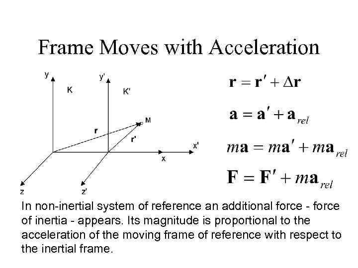
So, the effective net force on P1 in the frame of P2 is:
Since the effective net force is zero, the acceleration observed in the non-inertial frame must also be zero:
This confirms our kinematic result and provides a deeper, more satisfying physical picture. The "magic" of the straight-line motion is explained by the perfect cancellation of the real force of gravity by the fictitious force arising from the observer's own accelerated motion.
A More Tangible Example: Pendulum in an Accelerating Car
Let's see how this force-based approach works in a different context.
Chapter 11. Mechanics in Noninertial Frames
Please read the following text from 'Chapter 11. Mechanics in Noninertial Frames'. It begins by re-deriving the inertial force equation and then applies it to a concrete example.
Read the section 'Acceleration without Rotation' until the end of 'Example #1: A Pendulum in an Accelerating Car'. Focus on how the equation of motion is written in the non-inertial frame (eq. 11.5) by adding the inertial force term, -mA. Then, see how this leads to the concept of an 'effective gravity', g_{eff}, which determines the new equilibrium position.
This example shows how an object's equilibrium state (and thus its "trajectory" if it were oscillating) is altered in a non-inertial frame. The analysis is made simple by treating the fictitious force as just another force in the free-body diagram.
4. Beyond Linear Acceleration: A Glimpse into Rotating Frames
We have focused on linearly accelerating frames. You appreciate mathematical completeness, so it's important to acknowledge that this is a special case. The most general form of motion for a reference frame involves both linear acceleration and rotation.
When a frame rotates, the transformation equations become more complex, giving rise to additional, velocity-dependent fictitious forces. You may have heard of these: the Coriolis force and the centrifugal force. The full derivation is a beautiful exercise in vector calculus.
To give you a sense of this more general theory, the following video provides a rigorous, step-by-step derivation of the complete acceleration transformation for a frame that is both translating and rotating.
100th VIDEO❤️ RESOLVED-12 PSEUDO FORCE,ROTATING FRAME PHYSICS,CORIOLIS,CENTRIFUGAL,EULER FORCES
This video, from PHYSICS SIR JEE, presents a rigorous mathematical derivation of the full equation for acceleration in a rotating frame. This will show you where the famous Coriolis and centrifugal forces come from.
Watch the section from 02:28 to 13:44. This is a dense, mathematical derivation that relies heavily on vector cross products and time derivatives of rotating vectors. Don't worry about memorizing each step. Instead, focus on the structure of the derivation and the final result, which shows four distinct fictitious force terms: The linear term (-m\vec{a}_B), which we have already studied. The Coriolis term (-2m(\vec{\omega} imes \vec{v}_{ ext{rel}})). The Euler term (-m(\vec{\alpha} imes \vec{r})), due to angular acceleration. The centrifugal term (-m(\vec{\omega} imes (\vec{\omega} imes \vec{r}))).
This derivation shows how the simple relationship is just the beginning. The additional terms in a rotating frame are responsible for phenomena ranging from the circular motion of cyclones on Earth to the precession of a Foucault pendulum. We will not delve deeper into solving problems with these forces now, but having seen their origin is essential for a complete understanding of non-inertial frames. For a textual reference that also provides this derivation, you can consult the "Rotating Frames" section of the resource Non-inertial Frames, Translation and Rotating Coordinate ... (ID: LINK).
Conclusion
In this lesson, we moved from deriving transformation equations to actively applying them. By choosing a non-inertial frame wisely, we saw how a complex trajectory problem can be dramatically simplified.
Key Takeaways:
- The trajectory of an object as seen from a non-inertial frame can be found either kinematically, using , or dynamically, by adding the fictitious force to the real forces. Both methods yield the same result.
- For any two objects moving under the same constant acceleration field (like gravity), their relative motion is uniform and linear.
- This principle allows us to solve advanced problems, such as finding the minimum separation between projectiles, by transforming them into simpler geometric exercises.
- Linearly accelerating frames are a special case. General non-inertial motion includes rotation, which introduces additional fictitious forces like the Coriolis and centrifugal forces.
Preview of the Next Lesson:
We have now derived the equations and seen how to apply them to analyze motion from either the inertial or non-inertial perspective. In the next lesson, we will focus on problem-solving strategy. We will solve problems conceptually from both an inertial and a linearly accelerating frame to demonstrate the equivalence of the kinematic description and to develop an intuition for when one approach is more advantageous than the other.