Hello! Welcome to the first lesson in our module on Network Switching and Routing.
In our last session, we differentiated between hubs, switches, and routers by building a virtual network in Linux. You saw firsthand what these devices do and why they are fundamental to network communication. Today, we move from the virtual to the physical.
This lesson's learning outcome is to physically install a rack-mount switch or router and establish initial console access. This is a core, day-one skill for any data center or network role. Mastering this procedure—and being able to explain it clearly—is crucial for demonstrating job readiness. We'll start by watching technicians perform a real-world installation, and then we'll break down each step of the process.
1. From Box to Rack: The Physical Installation
Before a network device can forward a single packet, it needs a secure home. In a data center, this home is a standardized 19-inch equipment rack. Let's see what the process of installing equipment, or "racking and stacking," looks like in a professional environment.
A DAY in the LIFE of the DATA CENTRE | FULL CUSTOMER "RACK & STACK" with ASH & JAMES!
This video from Custodian Data Centres shows technicians performing a full customer installation. It gives you a great real-world view of the process.
Watch the segment from 04:34 to 05:58. Pay attention to how the technicians first install 'cage nuts' into the rack's vertical rails and then screw the network switches into place. This is the fundamental motion of racking a device.
As you saw, the process is systematic. It's not just about getting the device in; it's about doing it safely and correctly. Let's break down the components and steps involved.
Understanding the Environment: Racks and Rack Units
The framework you saw is a server rack. To ensure equipment from different manufacturers can fit together, the industry follows standards set by the Electronic Industries Alliance (EIA).
- Width: The standard width is 19 inches.
- Height: The vertical space is measured in Rack Units (U), where 1U = 1.75 inches. A typical full-size rack is 42U tall. Network switches are often 1U or 2U in height.
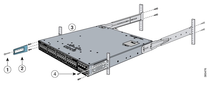
The Step-by-Step Installation Process
Now, let's look at a more detailed breakdown of the installation procedure.
Mastering the Art of Rack Mounting: A Comprehensive Guide to Switch Rack Solutions
The article 'Mastering the Art of Rack Mounting' from Fibermall provides a clear, step-by-step guide. We will focus on the practical installation steps.
Please read the section titled 'How to Install a Switch in a Rack Cabinet?'. Focus on the 'Steps in an Installation Procedure For Installation'. This provides the theoretical checklist for the practical work you saw in the video.
To summarize and combine the video and text, the key steps are:
- Preparation:
- Safety First: Ensure you can lift the device safely. Heavier equipment like servers or large switches should be installed with two people or a server lift.
- Plan the Location: Decide which 'U' space the device will occupy. For airflow and stability, best practice is to install heavier devices at the bottom of the rack.
- Attach Rack Ears: Securely screw the rack-mount brackets ("ears") to the sides of the switch or router.
- Mounting:
- Install Cage Nuts: As seen in the video, insert cage nuts into the square holes of the rack's vertical mounting rails at your chosen 'U' location. These provide the threaded holes for your screws.
- Position the Device: Rest the device on the rack rails or have a colleague hold it, aligning the holes on the rack ears with the cage nuts.
- Secure the Device: Screw the device into the rack. Start by loosely inserting all screws before tightening them fully to ensure proper alignment.

2. Establishing Initial Console Access
With the device physically installed, how do you configure it? You can't use the network yet because it has no IP address. This is where the console port comes in. It provides direct, out-of-band access to the device's command-line interface (CLI). This connection works even if the device's main networking functions are down, making it essential for initial setup and emergency troubleshooting.
The Hardware: Console Cable and Ports
The most common tool for this is a console cable, often a distinctive light blue color for Cisco devices.
- One end is an RJ45 connector that plugs into the switch's
CONSOLEport. - The other end is often a DB9 serial connector. Since modern laptops lack serial ports, you will almost always use a USB-to-Serial adapter.
Let's see this connection being made.
How to Connect Cisco Switch using Console Cable and PUTTY Step-by-Step
The video 'How to Connect Cisco Switch using Console Cable and PUTTY' demonstrates the entire process, from physical connection to CLI access. We'll watch it in two parts.
First, watch from 01:09 to 02:33. This part shows the physical act of connecting the RJ45 end of the console cable to the switch's console port and the USB end to the laptop.
The Software: PuTTY and Serial Connection Settings
Once connected, you need a terminal emulator program on your laptop to communicate with the switch. PuTTY is a free and widely used standard for this.
The connection is not plug-and-play. You must configure PuTTY to use the correct communication parameters. Given your ECE background, these settings should look familiar; they are the same parameters that define any basic serial communication, like UART protocols used with microcontrollers.
Let's walk through the configuration.
Accessing the CLI via PuTTY with a Console Connection - Cisco
This guide from Cisco provides an excellent, detailed walkthrough for configuring PuTTY for a console connection. It's a great reference to have.
Read through the steps in this document. It will show you: How to find the COM port: Your USB-to-Serial adapter is assigned a COM port by Windows. You must find this number in the 'Device Manager' to tell PuTTY where to send the data. How to configure PuTTY: Pay close attention to the specific serial connection settings required. How to log in: The final step to see the command prompt.
The critical settings for a serial connection in PuTTY are:
- Serial line: The
COMport you identified in Device Manager (e.g.,COM3). - Speed (baud):
9600(This is the most common default for many devices, though some, like the Cisco Business switches in the article, may use115200). This is the rate of data transmission. Both the switch and your computer must be set to the same speed. - Data bits:
8 - Stop bits:
1 - Parity:
None - Flow Control:
None
Once you apply these settings and open the connection, pressing Enter should display a login prompt from the switch's operating system, like User Name: or Switch>. You have successfully established console access!
Practice Application
Imagine you're on your first day at a new job. Your manager gives you a new 1U router and says, "Install this at the top of Rack 23. It has 3U of free space. Then, get it ready for me to configure."
Mentally walk through the entire process. What are the key actions you would take, from the moment you pick up the router to the moment you see a login prompt on your laptop? Consider these points:
- What safety checks do you perform?
- What hardware do you need besides the router itself? (Think screws, nuts, cables).
- What are the steps to physically secure it in the rack?
- What are the steps to connect your laptop?
- What are the three most important settings you need to configure in PuTTY?
Thinking through this sequence helps solidify the procedure in your mind, preparing you to perform it smoothly in a real-world setting.
Conclusion
Today, you've bridged the gap between network theory and the physical reality of a data center. You now understand the standardized process for installing hardware and the critical procedure for gaining initial access for configuration.
Key Takeaways:
- Network devices are installed in 19-inch racks, with their height measured in Rack Units (U).
- Installation involves attaching rack ears, positioning the device, and securing it to the rack rails using cage nuts and screws.
- Console access is essential for initial configuration and is achieved using a console cable and a terminal emulator like PuTTY.
- A successful console connection requires configuring the correct serial line (COM port) and communication parameters (baud rate, data bits, etc.).
You've successfully established a connection. So, what's next? In our next lesson, we will perform the initial configuration on a managed switch, including setting its hostname, management IP, and admin credentials, using the very console connection you learned to establish today.