Hello! Welcome back to your physics journey.
Introduction
In our last lesson, you learned the powerful technique of resolving a force vector into its perpendicular components. We saw how a single angled force could be broken down into its horizontal (x) and vertical (y) effects using trigonometry.
Today, we will apply that skill to one of the most classic problems in introductory physics: an object on an inclined plane, or a ramp. At first, this scenario seems much more complex than a flat surface. But by making one clever change to our setup, it becomes just as manageable.
Your goal is to construct a free-body diagram (FBD) for an object on an inclined plane. This means correctly identifying all the forces and representing them in a way that makes the problem easy to analyze. Mastering this diagram is the essential first step before we can calculate things like acceleration or friction on a slope. This skill is fundamental for analyzing everything from a skier on a hill to a delivery robot navigating a wheelchair ramp.
The Challenge: A Tilted World
When we drew free-body diagrams for objects on flat ground, things were straightforward. Gravity pulled straight down, and the normal force pushed straight up. But on a ramp, things get tricky.
Let's start by clarifying one of the most common points of confusion: the normal force.
This short reading from The Physics Classroom explains the 'abnormal' behavior of the normal force on an incline. It's a crucial first concept to grasp.
Read the section titled 'The Abnormal Normal Force'. The key takeaway is the definition of the normal force: it's always perpendicular to the surface the object is on.
So, on a ramp, the normal force points perpendicular to the ramp's surface, while gravity still points straight down. If we used a standard horizontal/vertical coordinate system, we'd have to resolve multiple forces into components. This is messy.
There's a much better way. We rotate our coordinate system.
Breaking the Force of Gravity into its Components on an Incline
The key to solving inclined plane problems is to choose a 'smarter' set of axes. This video from Flipping Physics explains why we tilt our coordinate system to align with the ramp.
Watch the clip from 0:40 to 2:16. Focus on the reason for tilting the axes: it simplifies the problem so that only one force (gravity) needs to be resolved into components, and the object's acceleration will be along one of the new axes.
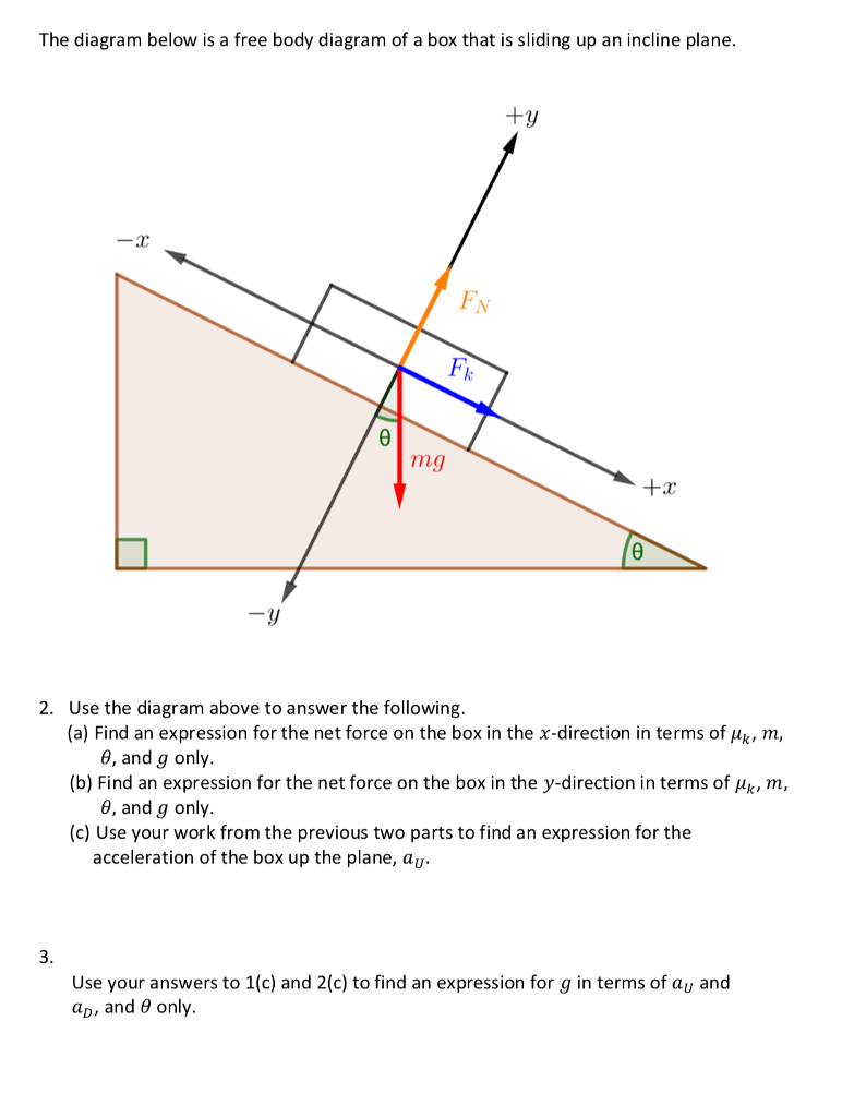
By tilting our axes, we now have a system where the normal force is entirely in the new 'y' direction (perpendicular to the ramp), and friction is entirely in the new 'x' direction (parallel to the ramp). The only force that's now at a funny angle is gravity.
Resolving the Force of Gravity
Since gravity is the only force not aligned with our new, tilted axes, we must resolve it into components that are aligned:
- A component perpendicular to the plane ().
- A component parallel to the plane ().
This is where your new vector skills come into play. The process involves some simple geometry and trigonometry.
Breaking the Force of Gravity into its Components on an Incline
This next segment from the same Flipping Physics video is a fantastic, step-by-step guide to resolving the gravity vector on an incline. It's a bit longer, but it's the core of today's lesson and directly addresses your interest in understanding the 'why'.
Please watch from 2:16 to 5:53. The video will show you: How to draw the parallel and perpendicular components of gravity. A geometric proof showing that the angle of the incline (\theta) is the same angle we use to resolve the gravity vector. This is a great example of applying math to see the 'first principles' of the physics. How to use SOH CAH TOA to derive the formulas for the components.
Let's summarize the crucial results from that video. For an object of mass on a plane inclined at an angle :
- The force of gravity is .
- The component of gravity perpendicular to the plane is . This component pushes the object into the ramp.
- The component of gravity parallel to the plane is . This component tries to pull the object down the ramp.
A Critical Connection to Last Lesson:
Notice that for the parallel component () we use , and for the perpendicular component () we use . This might seem opposite to what we did in the last lesson. But remember the fundamental rule: the component adjacent to the angle uses cosine, and the component opposite uses sine. In the force triangle on an incline, the perpendicular component is adjacent to , hence cosine. The parallel component is opposite, hence sine. Always trust the geometry, not a memorized formula pattern!
Constructing the Full Free-Body Diagram
Now we have all the pieces. A complete free-body diagram for an object on an inclined plane replaces the single gravity vector with its two components.
Let's follow a clear procedure, based on the process outlined in the OpenStax textbook.
- Represent the object as a dot.
- Draw the tilted coordinate axes: one parallel to the slope, one perpendicular to it.
- Draw the forces that align with your axes:
- Normal Force (): Points directly along the perpendicular axis, away from the surface.
- Friction (): Points directly along the parallel axis, opposing the direction of motion (or potential motion). If the object is sliding down, friction points up the ramp. If it's being pushed up, friction points down.
- Draw the components of gravity:
- Draw along the perpendicular axis, pointing into the surface.
- Draw along the parallel axis, always pointing down the ramp.
- Do not draw the original gravity vector ()! It has now been replaced by its components.
Here is an image that puts it all together visually.

The result is a diagram where all forces lie perfectly on the tilted x and y axes. We have successfully turned a 2D problem into two separate 1D problems, which we'll solve in the next lesson.
Examples in Action
Let's look at a few common scenarios to see how the FBD changes.
Scenario 1: Object sliding down an incline
The force of kinetic friction () will point up the incline, opposing the downward slide.
Scenario 2: Object held at rest by a rope
If a rope is pulling up the incline to keep the box from sliding, we would add a Tension force () pointing parallel to the ramp, up the slope. The friction in this case would be static friction.
To see these diagrams animated, watch these quick clips.
These short clips from Bozeman Science show animated free-body diagrams for a car on a ramp in two different situations.
Watch from 5:14 to 6:12. The first part shows a car accelerating down a ramp, and the second shows a car held motionless by a tension force. Pay attention to how the forces are drawn for each case.
Conclusion
Excellent work today. You've learned how to deconstruct a complex physical situation—an object on a ramp—into a clear, analysis-ready diagram. This is a pivotal skill in physics and engineering.
Key Takeaways:
- For inclined plane problems, always tilt your coordinate system to be parallel and perpendicular to the surface.
- The normal force is always perpendicular to the surface.
- The force of gravity () must be resolved into a parallel component () and a perpendicular component ().
- Your final FBD should show all forces aligned with the tilted axes, with the original gravity vector replaced by its components.
Connection to Robotics:
Imagine you are programming a wheeled robot to climb a ramp. Your program needs to know how much power to send to the motors. This power must be enough to overcome the parallel component of gravity () and any friction. The free-body diagram you learned to draw today is the absolute first step an engineer would take to calculate those required forces and torques. Without it, you're just guessing.
Preview of the Next Lesson:
Now that we can confidently draw the FBD for an object on an incline, we're ready to use it. In our next lesson, we will apply Newton's Second Law () to our tilted axes. We'll set up equations for the parallel and perpendicular directions separately to solve for unknowns like the object's acceleration or the force of friction.