Welcome to the next step in your database design journey! In our previous lesson, you learned how to synthesize a complete Entity-Relationship Diagram (ERD) from a set of business requirements. You successfully translated a business scenario into a structured diagram, incorporating entities, attributes, relationships, and cardinality.
This lesson focuses on the flip side of creation: verification. Now that you can build an ERD, it's crucial to learn how to critically evaluate one to ensure it is both complete and correct. You will learn to act as a reviewer, checking a given ERD against its original business rules to spot errors, omissions, and design flaws. This skill is vital for catching issues early in the design process, saving significant time and effort before any implementation begins.
By the end of this 60-minute lesson, you will be able to systematically verify an ERD against its business requirements for both completeness and correctness.
1. The Art of Verification: A Framework for Review
Verifying an ERD isn't a random process; it's a systematic check to ensure the diagram is a faithful model of the business reality. We can break this down into a structured review process that covers completeness, correctness, and adherence to design principles.
A good way to approach this is with a validation checklist. The following resource provides a practical framework for reviewing an ERD, which we will adopt for this lesson.
How to Draw an ER Diagram: Refine and validate your diagram
This section from Miro's guide provides an excellent checklist for validating an ERD.
Please read the section titled "Step 5: Refine and validate your diagram". Focus on the "Validation checklist" and the section on "Peer review process". As you read, think about how you would use these questions to critique a diagram: Completeness: Does the diagram capture everything it needs to? Correctness: Are the connections and rules represented accurately? Functionality: Can the design support the required operations (e.g., generating a report, finding information)?
A Systematic Checklist for ERD Verification
Based on the reading and established database design principles, here is a checklist you can use to verify any ERD:
-
Completeness Check:
- All Entities Included? Compare the nouns in the business description to the entities in the ERD. Has anything been missed?
- All Attributes Included? Does each entity have the necessary attributes to store the required information? Are there any descriptive details from the scenario that haven't been captured?
- All Relationships Included? Have all the interactions (verbs) between entities described in the rules been modeled as relationships?
-
Correctness Check:
- Entities vs. Attributes: Is anything modeled as an entity when it should be a simple attribute (e.g., modeling 'City' as an entity when it's just a property of 'Customer')? Conversely, is something modeled as an attribute when it should be an entity (e.g., storing 'author_name' as a text field in a
BOOKentity instead of creating a separateAUTHORentity)? - Relationship Cardinality: Is the cardinality (1:1, 1:M, M:N) for each relationship correct according to the business rules? For example, if the rule says "a customer can have many orders," is the relationship a 1:M?
- Relationship Participation: Is the participation (mandatory/optional) correct? For example, if an employee must belong to a department, is the participation from
EMPLOYEEtoDEPARTMENTshown as mandatory? - Key Placement: Does every entity have a primary key (PK)? For 1:M relationships, is the foreign key (FK) correctly placed on the "many" side?
- M:N Relationships: Have all many-to-many relationships been properly resolved with a composite (or bridge) entity for implementation? A direct M:N link is a red flag in a logical or physical ERD.
- Entities vs. Attributes: Is anything modeled as an entity when it should be a simple attribute (e.g., modeling 'City' as an entity when it's just a property of 'Customer')? Conversely, is something modeled as an attribute when it should be an entity (e.g., storing 'author_name' as a text field in a
2. Putting It to Practice: Verifying an ERD
Let's apply this checklist to a practical example. Below is a set of business rules and a corresponding ERD that a junior designer has created. Your task is to act as the senior designer and verify the diagram.
Business Scenario:
A company needs a database to track its sales operations.
- Some salespeople are managers who supervise other salespeople. A salesperson can have one manager.
- Each salesperson is an agent for many customers, but each customer is assigned to only one salesperson.
- A customer can place many orders.
- An order can contain many different products, and a single product can appear on many different orders.
- A product is assembled from many parts. A part can be used in the assembly of many different products.
- A supplier can supply many parts, and a part can be supplied by many different suppliers.
- An employee can be involved in assembling many products, and each product can be assembled by many employees.
Proposed ERD:
Now, examine the diagram below created from this scenario.

Take a few minutes and use our verification checklist to analyze this diagram. Does it fully and correctly model the business rules? Identify any errors or areas for improvement.
Click here for a detailed verification analysis
Let's walk through the verification process for this ERD.
-
Completeness Check:
- Entities: All key nouns (Salesperson, Customer, Order, Product, Part, Supplier, Employee) are present as entities. This looks good.
- Relationships: All key verbs/interactions (Manages, Agent for, Places, Lists, Assembled into, Supplies, Assembles) are present. This also looks good.
-
Correctness Check:
SalespersonmanagesSalesperson(Unary): The rule is "Some salespeople are managers... A salesperson can have one manager." The ERD shows a 1:M relationship from a salesperson (as a manager) to other salespeople. This is correct.SalespersonisAgent forCustomer: The rule is "Each salesperson is an agent for many customers, but each customer is assigned to only one." The ERD shows a 1:M relationship. This is correct.CustomerPlacesOrder: The rule is "A customer can place many orders." The ERD shows a 1:M relationship. This is correct.OrderListsProduct: The rule is "An order can contain many different products, and a single product can appear on many different orders." This is a many-to-many (M:N) relationship. The ERD shows a direct M:N link. This is an error. As you learned previously, direct M:N relationships cannot be implemented in a relational database. This must be resolved by creating a composite entity (e.g.,ORDER_ITEM) betweenORDERandPRODUCT.ProductAssembled intoPart: The rule is "A product is assembled from many parts. A part can be used in the assembly of many different products." This is another M:N relationship. The diagram again shows a direct M:N link, which is an error. It requires a composite entity (e.g.,BILL_OF_MATERIALS).SupplierSuppliesPart: The rule is "A supplier can supply many parts, and a part can be supplied by many different suppliers." Another M:N relationship, another error in the diagram. It needs a composite entity (e.g.,SUPPLY_LIST).EmployeeAssemblesProduct: The rule is "An employee can be involved in assembling many products, and each product can be assembled by many employees." A final M:N relationship that is incorrectly modeled directly. This needs a composite entity (e.g.,ASSEMBLY_RECORD).
Conclusion of Verification: The diagram correctly identifies the entities and the types of relationships but fails to correctly model the M:N relationships for implementation. A senior designer would reject this ERD and ask the junior designer to resolve all M:N relationships using composite entities.
3. Understanding Common Modeling Errors
The mistakes found in the previous exercise are very common. It's crucial to learn to spot them. The resource below discusses several classic errors in ER modeling, including confusing entities with attributes and modeling relationships incorrectly.
[PDF] A Practical Guide to Entity-Relationship Modeling
This section of a guide by Song and Froehlich discusses common errors in ERD modeling with clear examples.
Read the section "Errors in Modeling" (page 228). Pay close attention to the explanations for each incorrect diagram in Figure 6: (a) Selection of wrong verb as relationship. (b) Modeling an attribute as an entity. (c) Modeling an indirect or redundant relationship. (d) Modeling an event (like a payment) as a relationship instead of an entity. This will deepen your understanding of the kinds of logical errors to look for during verification.
4. Your Turn: Final Practice
Here is one final practice exercise. The image below contains the same business rules as before, but this time with a different, partially complete ERD drawn using Chen's notation.
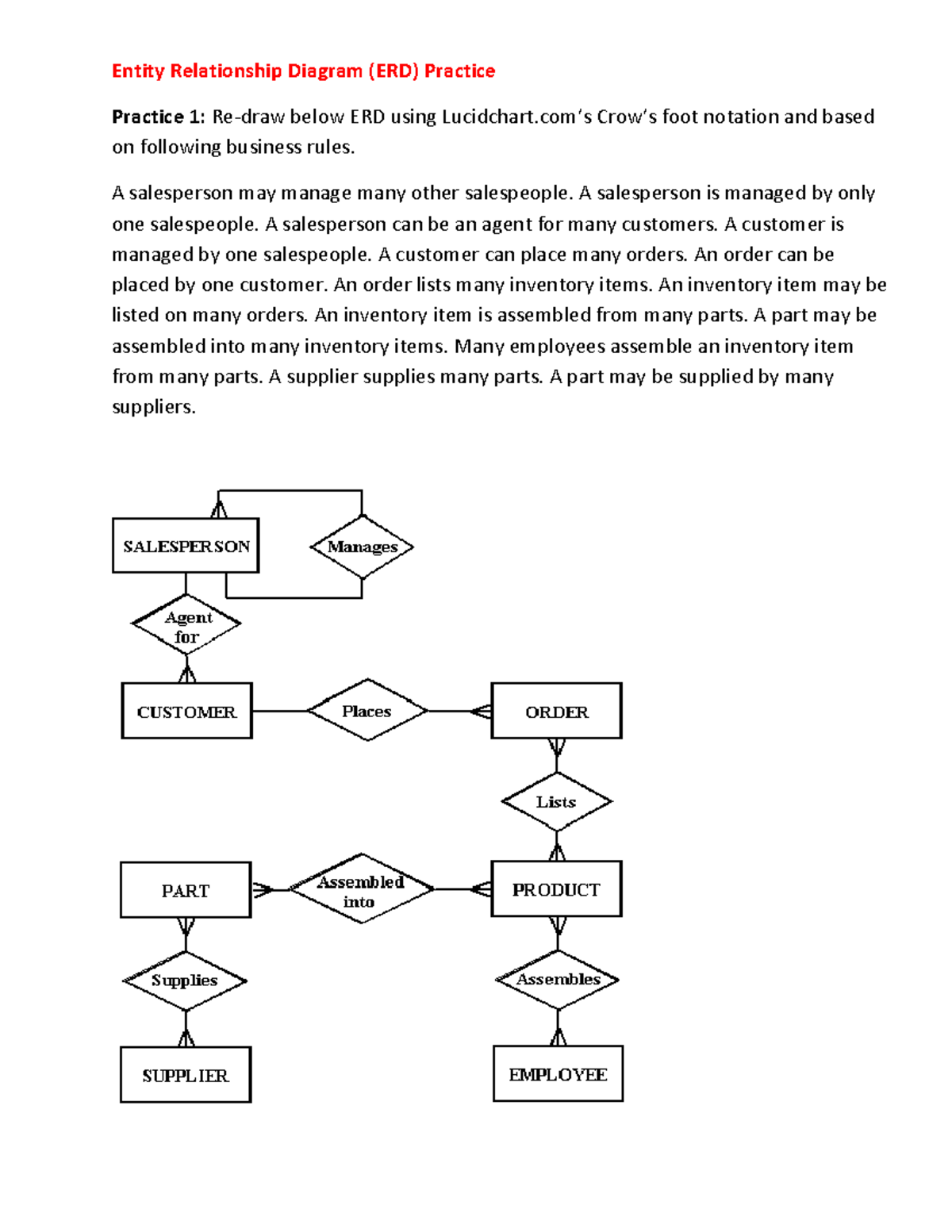
Your task is to analyze this diagram against the business rules.
- Does this Chen-style ERD represent the M:N relationships more accurately at a conceptual level than the previous Crow's Foot diagram?
- What is missing from this diagram to make it a complete representation of the business rules? (Hint: look at the relationships and think about cardinality).
Take about 10 minutes to analyze it and formulate your answer.
Click here to check your analysis
-
Representation of M:N Relationships:
- Yes, this diagram represents the M:N relationships more accurately at a conceptual level. In Chen's notation, a relationship is its own object (the diamond). The relationships
lists,assembled from,supplies, andassemblesare correctly identified as single interactions between two entities. This is conceptually valid before you think about implementation. The previous Crow's Foot diagram was flawed because it tried to use an implementation-focused notation (which implies FKs) to draw a relationship type that can't be directly implemented.
- Yes, this diagram represents the M:N relationships more accurately at a conceptual level. In Chen's notation, a relationship is its own object (the diamond). The relationships
-
What's Missing?
- Cardinality and Participation: The biggest missing piece is the cardinality and participation constraints. The diagram shows the relationships exist, but it doesn't specify the business rules (1:1, 1:M, M:N, or mandatory/optional participation). Without these markers, the diagram is incomplete and ambiguous. For example, it doesn't tell us that a
Customercan place manyOrders, or that anOrdermust be placed by exactly oneCustomer. - Attributes: The diagram is also missing all attributes, including primary and foreign keys, which would be necessary for a logical or physical model.
- Cardinality and Participation: The biggest missing piece is the cardinality and participation constraints. The diagram shows the relationships exist, but it doesn't specify the business rules (1:1, 1:M, M:N, or mandatory/optional participation). Without these markers, the diagram is incomplete and ambiguous. For example, it doesn't tell us that a
This exercise shows that verification isn't just about spotting outright errors but also about identifying incompleteness. A diagram is only as good as the business details it captures.
Conclusion
In this lesson, you transitioned from being a creator of ERDs to a critical reviewer. You learned that verification is a crucial, systematic process that ensures a database design is a true and complete reflection of business requirements.
Key Takeaways:
- Verification is a systematic process: Use a checklist to check for completeness (all entities, attributes, relationships) and correctness (proper modeling of concepts, cardinality, and keys).
- Spotting common errors is key: Be on the lookout for improperly modeled entities/attributes and, most importantly, unresolved M:N relationships in logical/physical diagrams.
- A diagram's purpose matters: A conceptual diagram (like one in Chen's notation) might show M:N relationships directly, but a logical or physical diagram (often in Crow's Foot) must resolve them with composite entities.
You have now completed all the topics related to creating and verifying ERDs. The next series of lessons will take you "inside" the tables you've designed. We will begin with normalization, a formal process for organizing attributes within entities to minimize data redundancy and prevent common data management problems called anomalies. This will add another layer of quality and robustness to your database designs.